


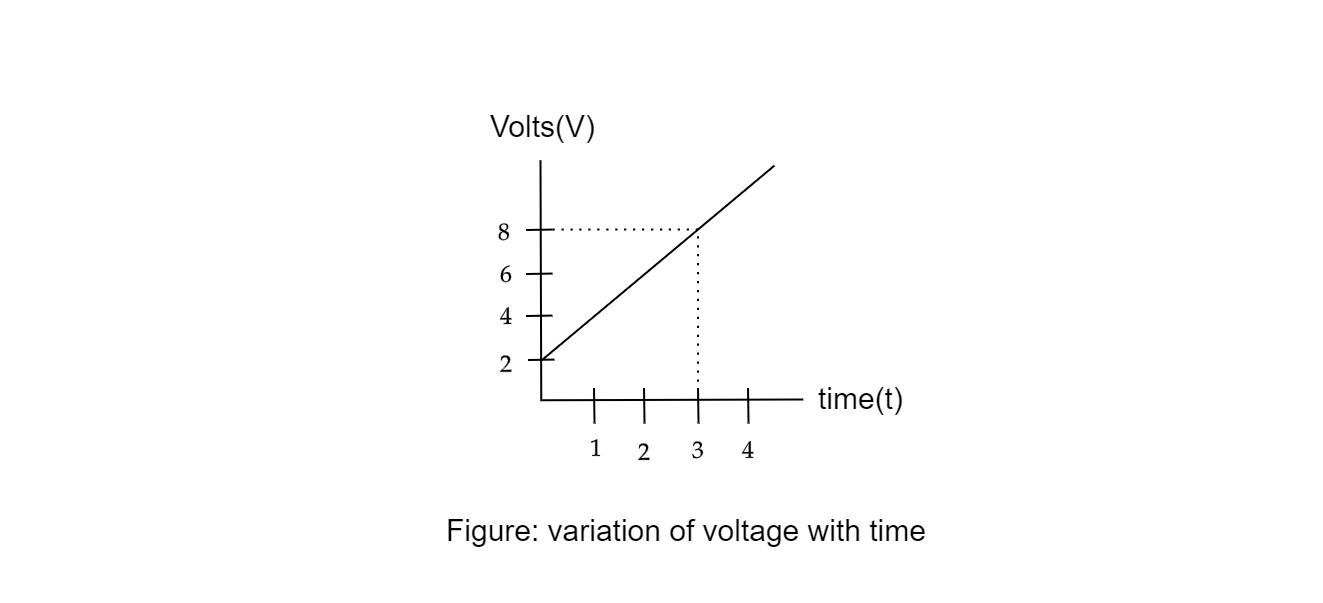
A circuit element is placed in a closed box. At a time, t=0, a constant current generator supplying current of 1 amp, is connected across the box. Potential difference across the box varies according to the graph shown in figure. The element in the box has:
(a) resistance of 2 ohms
(b) battery of emf 6V
(c) inductance of 2H
(d) capacitance of 0.5F
Answer
233.1k+ views
Hint:
1.Potential difference is rising or changing with time. And current is constant, therefore, circuit elements can’t be resistance and inductance.
2. Potential difference is changing so the battery emf can’t be constant 6 voltage. It should be time varying.
Formula Used:
1.For a purely resistive circuit element. we know, V=IR …… (1)
Where,
V = voltage across resistor
R=resistance in the circuit
I = current in the circuit
2. For a purely inductive circuit we know, $ - I\dfrac{{di}}{{dt}} = Voltage$ …… (2)
Where,
I = inductance across the inductor
V = Voltage across inductive coil
3. For a purely capacitive circuit we know, $\dfrac{{dq}}{{dt}} = C\dfrac{{dV}}{{dt}}$ $ \Rightarrow \dfrac{i}{C} = \dfrac{{dV}}{{dt}}$ …… (3)
Where,
Q = charge stored in capacitor
V = Voltage across plates
i = current in the circuit
C= capacitance
Complete step by step answer:
Let’s find the correct by rejecting the wrong choices: Hit and trial approach:
Step 1:
From equation (1) we can say with time, Voltage would be constant. Since there is no time term in it. Therefore, the above graph should have 0 slope. But slope is non zero. So, it can’t be a resistor.
\[ \Rightarrow \]Hence, option (a) Not Possible
Step 2:
Given Voltage is time varying with constant slope. But in option (b) it says emf is constant= 6V
\[ \Rightarrow \]Hence, option (b) Not Possible
Step 3:
From equation (2), we can say with time, current is also changing. But in question, it is given current is constant and equals 1 amp. Therefore, circuits can’t be inductive.
\[ \Rightarrow \]option (b) Not Possible
Step 4:
From equation (3), we can say with time Voltage is varying and current is constant. Therefore, conditions satisfied for a capacitive circuit. So, Circuit is capacitive.
Step 5:
From the graph, we can see the graph is constant. So, slope of graph=$\dfrac{i}{C} = \dfrac{{dV}}{{dt}}$
Evaluating slope of graph using 2-point slope form we get,
$\dfrac{i}{C} = \dfrac{{{y_2} - {y_1}}}{{{t_2} - {t_1}}} = \dfrac{{8 - 2}}{{3 - 0}} = 2$ where $({x_1},{y_1})$ and $({x_2},{y_2})$ are two separate points ……. (4)
Step 6:
Substitute value of current i=1 amp, in equation (4) we get,
$\dfrac{1}{2} = C \Rightarrow C = 0.5F$ required capacitance of circuit.
Final Answer
Hence, option (d) capacitance of 0.5F
Note: Sometimes information given from a question is too less to decide how to proceed toward solution of the problem. Therefore, one should find what not to do first using Hit and trial approach. Also one should get an intuition that as current is constant basically with time more and more charge is provided to the circuit element. As capacitance is constant(only depends on the geometry of the capacitor) the charge to voltage ratio should be constant and as charge increases potential difference should increase too.
Recently Updated Pages
JEE Main 2023 April 6 Shift 1 Question Paper with Answer Key
JEE Main 2023 April 6 Shift 2 Question Paper with Answer Key
JEE Main 2023 (January 31 Evening Shift) Question Paper with Solutions [PDF]
JEE Main 2023 January 30 Shift 2 Question Paper with Answer Key
JEE Main 2023 January 25 Shift 1 Question Paper with Answer Key
JEE Main 2023 January 24 Shift 2 Question Paper with Answer Key
Trending doubts
JEE Main 2026: Session 2 Registration Open, City Intimation Slip, Exam Dates, Syllabus & Eligibility
JEE Main 2026 Application Login: Direct Link, Registration, Form Fill, and Steps
Understanding the Angle of Deviation in a Prism
Hybridisation in Chemistry – Concept, Types & Applications
How to Convert a Galvanometer into an Ammeter or Voltmeter
Understanding Uniform Acceleration in Physics
Other Pages
JEE Advanced Marks vs Ranks 2025: Understanding Category-wise Qualifying Marks and Previous Year Cut-offs
Dual Nature of Radiation and Matter Class 12 Physics Chapter 11 CBSE Notes - 2025-26
Understanding the Electric Field of a Uniformly Charged Ring
JEE Advanced Weightage 2025 Chapter-Wise for Physics, Maths and Chemistry
Derivation of Equation of Trajectory Explained for Students
Understanding Electromagnetic Waves and Their Importance