


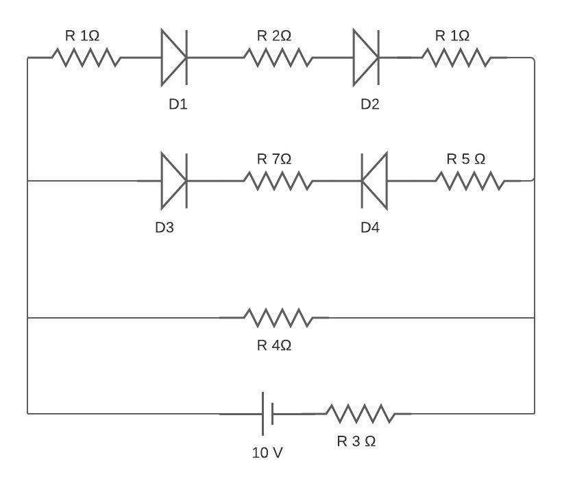
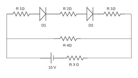
All diodes are ideal. The current flowing in $2\Omega $resistor connected between the diodes ${D_1}$ and ${D_2}$is then:
A) 1A
B) 2A
C) 3A
D) Zero
Answer
232.8k+ views
Hint: A diode is a device which allows current to pass in only one direction i.e. it will allow the current to pass in the forward bias only. The resistance for the diode in forward bias is zero and in reverse bias is infinity.
Complete step by step answer:
Here in the second line the diode D4 is reverse bias so there will be no current flowing in it.
The resistance is in series with each other so, the equivalent resistance will be:
${R_{eq}} = 1\Omega + 2\Omega + 1\Omega $;
The equivalent resistance would be:
$ \Rightarrow {R_{eq}} = 4\Omega $;
Now the resistors $4\Omega $ and $4\Omega $ are in parallel with each other. So, the equivalent resistance is:
${R_{eq1}} = \dfrac{{{R_1}{R_2}}}{{{R_1} + {R_2}}}$ ;
Put in the given values of resistance in the above equation:
$ \Rightarrow {R_{eq1}} = \dfrac{{4 \times 4}}{{4 + 4}}$;
$ \Rightarrow {R_{eq1}} = \dfrac{{16}}{8} = 2\Omega $;
The resistance$2\Omega $and $3\Omega $are in series with each other:
${R_{eq}} = 2\Omega + 3\Omega $;
\[ \Rightarrow {R_{eq}} = 5\Omega \];
Now we know the relation between the current, Voltage and Resistor respectively:
${I_{eq}} = \dfrac{V}{{{R_{eq}}}}$ ;
Put in the given values in the above equation and solve:
$ \Rightarrow {I_{eq}} = \dfrac{{10}}{5}$;
The equivalent current is:
$ \Rightarrow {I_{eq}} = 2A$;
Current in the $2\Omega $ resistor would be 1A.
Option B is correct. The current flowing in $2\Omega $resistor connected between the diodes ${D_1}$ and ${D_2}$is 1A.
Note: Here we need to solve the circuit. First find the equivalent resistance in row 1 which is in series. Then resistance in first row/wire would be in parallel with the resistance in second row/wire. After that the two resistances i.e. $2\Omega $ and $3\Omega $ would be in series with each other. Apply the formula V=IR and solve.
Recently Updated Pages
JEE Main 2023 April 6 Shift 1 Question Paper with Answer Key
JEE Main 2023 April 6 Shift 2 Question Paper with Answer Key
JEE Main 2023 (January 31 Evening Shift) Question Paper with Solutions [PDF]
JEE Main 2023 January 30 Shift 2 Question Paper with Answer Key
JEE Main 2023 January 25 Shift 1 Question Paper with Answer Key
JEE Main 2023 January 24 Shift 2 Question Paper with Answer Key
Trending doubts
JEE Main 2026: Session 2 Registration Open, City Intimation Slip, Exam Dates, Syllabus & Eligibility
JEE Main 2026 Application Login: Direct Link, Registration, Form Fill, and Steps
JEE Main Marking Scheme 2026- Paper-Wise Marks Distribution and Negative Marking Details
Understanding the Angle of Deviation in a Prism
Hybridisation in Chemistry – Concept, Types & Applications
How to Convert a Galvanometer into an Ammeter or Voltmeter
Other Pages
JEE Advanced Marks vs Ranks 2025: Understanding Category-wise Qualifying Marks and Previous Year Cut-offs
Dual Nature of Radiation and Matter Class 12 Physics Chapter 11 CBSE Notes - 2025-26
Understanding Uniform Acceleration in Physics
Understanding the Electric Field of a Uniformly Charged Ring
JEE Advanced Weightage 2025 Chapter-Wise for Physics, Maths and Chemistry
Derivation of Equation of Trajectory Explained for Students