


What is the calibration of a voltmeter by a potentiometer? Draw the necessary circuit diagram.
Answer
232.8k+ views
Hint: A potentiometer is an instrument used to measure the potential difference and e.m.f, to compare the e.m.f and the internal resistance of a cell. It consists of a uniform wire of manganin or constantan of $10m$ length. An instrument is calibrated to maintain its accuracy and precision over long term use.
Complete Step by step solution:
An instrument is calibrated to avoid errors in the performance and increase the accuracy of the instrument. Here we are calibrating a voltmeter. The main errors that are observed in a voltmeter reading are
1. Mechanical errors due to manufacturing defects.
2. Parallax error
3. Asymmetry in the voltmeter spring.
The potentiometer can be used to increase the accuracy in the value of potential difference.
When we use a potentiometer to check the errors in the observations of a voltmeter, it is called the calibration of the voltmeter.
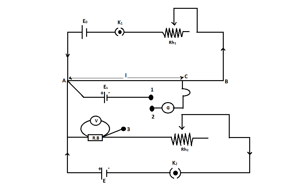
The figure shows the diagram for the calibration of the voltmeter using a potentiometer.
It consists of a primary circuit that is shown in the above section. The positive terminal of the standard cell is connected to point A in the secondary circuit. Point A is the high potential end. The negative terminal of the standard cell is connected to the first terminal of a two-way key. As shown in the figure, the cell $E$, key, rheostat, and resistance box is connected in a series connection. One end of the resistance box(high potential end) is connected to the point of high potential $A$ and the point of the resistance box having low potential is connected to the third terminal of a two-way key.
The voltmeter that needs the calibration is connected across the resistance box. The central terminal of the two-way key is connected to a galvanometer. And the other end of the galvanometer is connected with a jockey.
After completing the primary circuit as shown in the diagram, insert the plug between the terminal $1$ and the terminal $2$. Now we have to find the balancing length for the standard cell ${E_s}$.
Let ${l_0}$be the balancing length for ${E_s}$.
${E_s} = k{l_0}$
Where $k$ is the potential gradient
From the above equation, we can write
$k = \dfrac{{{E_s}}}{{{l_0}}}$
We can find $k$ it by standardizing the cell.
Now we have to remove the plug between the terminals $1$ and $2$. And we have to insert it between the terminal $2$ and $3$. After closing the key ${K_2}$ take the suitable resistance from the resistance box. Using the rheostat adjust the current passing through the resistance and note down the deflection of the voltmeter. Let it be $V$. This value will not be accurate, it contains an error. The real value of potential difference can be obtained by the potentiometer. We have to find the corresponding balancing length. Let this balancing length be ${l_2}$.
By applying the principle of the potentiometer, the actual value of potential difference can be written as,
$V' = k{l_2}$
We know that the value of $k$ is $k = \dfrac{{{E_s}}}{{{l_0}}}$
Substituting, we get
$V' = \left( {\dfrac{{{E_s}}}{{{l_0}}}} \right){l_2}$
The error in the value observed by the voltmeter can be written as,
$\Delta V = V - V'$
Using the resistance box and the rheostat, different values of voltmeter can be observed. The corresponding potential difference can also be obtained by using the potentiometer. The difference between the observation of the voltmeter and the potential difference by the potentiometer can be used to find the error.
Note:
The curve plotted using the voltmeter readings and the corresponding errors are called the calibration curve of the voltmeter. This curve does not have a particular shape. It can be of random shape. A voltmeter is used to measure the potential difference across two points.
Complete Step by step solution:
An instrument is calibrated to avoid errors in the performance and increase the accuracy of the instrument. Here we are calibrating a voltmeter. The main errors that are observed in a voltmeter reading are
1. Mechanical errors due to manufacturing defects.
2. Parallax error
3. Asymmetry in the voltmeter spring.
The potentiometer can be used to increase the accuracy in the value of potential difference.
When we use a potentiometer to check the errors in the observations of a voltmeter, it is called the calibration of the voltmeter.
The figure shows the diagram for the calibration of the voltmeter using a potentiometer.
It consists of a primary circuit that is shown in the above section. The positive terminal of the standard cell is connected to point A in the secondary circuit. Point A is the high potential end. The negative terminal of the standard cell is connected to the first terminal of a two-way key. As shown in the figure, the cell $E$, key, rheostat, and resistance box is connected in a series connection. One end of the resistance box(high potential end) is connected to the point of high potential $A$ and the point of the resistance box having low potential is connected to the third terminal of a two-way key.
The voltmeter that needs the calibration is connected across the resistance box. The central terminal of the two-way key is connected to a galvanometer. And the other end of the galvanometer is connected with a jockey.
After completing the primary circuit as shown in the diagram, insert the plug between the terminal $1$ and the terminal $2$. Now we have to find the balancing length for the standard cell ${E_s}$.
Let ${l_0}$be the balancing length for ${E_s}$.
${E_s} = k{l_0}$
Where $k$ is the potential gradient
From the above equation, we can write
$k = \dfrac{{{E_s}}}{{{l_0}}}$
We can find $k$ it by standardizing the cell.
Now we have to remove the plug between the terminals $1$ and $2$. And we have to insert it between the terminal $2$ and $3$. After closing the key ${K_2}$ take the suitable resistance from the resistance box. Using the rheostat adjust the current passing through the resistance and note down the deflection of the voltmeter. Let it be $V$. This value will not be accurate, it contains an error. The real value of potential difference can be obtained by the potentiometer. We have to find the corresponding balancing length. Let this balancing length be ${l_2}$.
By applying the principle of the potentiometer, the actual value of potential difference can be written as,
$V' = k{l_2}$
We know that the value of $k$ is $k = \dfrac{{{E_s}}}{{{l_0}}}$
Substituting, we get
$V' = \left( {\dfrac{{{E_s}}}{{{l_0}}}} \right){l_2}$
The error in the value observed by the voltmeter can be written as,
$\Delta V = V - V'$
Using the resistance box and the rheostat, different values of voltmeter can be observed. The corresponding potential difference can also be obtained by using the potentiometer. The difference between the observation of the voltmeter and the potential difference by the potentiometer can be used to find the error.
Note:
The curve plotted using the voltmeter readings and the corresponding errors are called the calibration curve of the voltmeter. This curve does not have a particular shape. It can be of random shape. A voltmeter is used to measure the potential difference across two points.
Recently Updated Pages
JEE Main 2023 April 6 Shift 1 Question Paper with Answer Key
JEE Main 2023 April 6 Shift 2 Question Paper with Answer Key
JEE Main 2023 (January 31 Evening Shift) Question Paper with Solutions [PDF]
JEE Main 2023 January 30 Shift 2 Question Paper with Answer Key
JEE Main 2023 January 25 Shift 1 Question Paper with Answer Key
JEE Main 2023 January 24 Shift 2 Question Paper with Answer Key
Trending doubts
JEE Main 2026: Session 2 Registration Open, City Intimation Slip, Exam Dates, Syllabus & Eligibility
JEE Main 2026 Application Login: Direct Link, Registration, Form Fill, and Steps
JEE Main Marking Scheme 2026- Paper-Wise Marks Distribution and Negative Marking Details
Understanding the Angle of Deviation in a Prism
Hybridisation in Chemistry – Concept, Types & Applications
How to Convert a Galvanometer into an Ammeter or Voltmeter
Other Pages
JEE Advanced Marks vs Ranks 2025: Understanding Category-wise Qualifying Marks and Previous Year Cut-offs
Dual Nature of Radiation and Matter Class 12 Physics Chapter 11 CBSE Notes - 2025-26
Understanding Uniform Acceleration in Physics
Understanding the Electric Field of a Uniformly Charged Ring
JEE Advanced Weightage 2025 Chapter-Wise for Physics, Maths and Chemistry
Derivation of Equation of Trajectory Explained for Students