


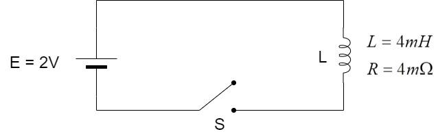
The cell in the circuit shown in the figure is ideal. The coil has an inductance of 4mH and resistance of $2m\Omega$. The switch is closed at t = 0. The amount of energy stored in the inductor at t = 2s is (take e = 3)
A) $\dfrac{4}{3}J$
B) $\dfrac{8}{9} \times {10^3}J$
C) $\dfrac{8}{3} \times {10^{ - 3}}J$
D) $2 \times {10^3}J$
Answer
232.8k+ views
Hint: When inductor is present in a circuit, the current in the circuit does not reach the maximum value immediately when the switch is closed. The current reaches its maximum value by taking some time since the inductor causes a lag in the current due to the phenomenon of self-inductance.
Complete step by step answer:
An inductor is a passive electrical device which consists of a coiled wire with several turns wound over a material known as core. The inductor behaves like a normal conductor when direct current flows through it but it offers obstruction to alternating current, which is termed as reactance.
The obstruction offered by the inductor is because of the existence of an opposing emf in the inductor which tends to oppose the alternating current flowing through it. This emf is called back emf.
The back emf exists because of the Faraday’s law which states that –
When magnetic flux linked with the coil changes, an emf is induced across its ends.
$\varepsilon = - \dfrac{{d\phi }}{{dt}}$
Now, when alternating current flows through the inductor, the magnetic flux linked with the inductor changes with the current. This results in an emf in the inductor known as the back emf.
Since, magnetic flux linked with the coil is proportional to the current through the coil, we have –
Back emf,
$v = - L\dfrac{{di}}{{dt}}$
where L = constant known as the coefficient of self-inductance (or simply, inductance) of the inductor measured in henry (H) and $\dfrac{{di}}{{dt}}$ = rate of change of current through the coil.
With the above equation, we obtain the relation for current developed through the inductor is given by –
$i = - \dfrac{E}{R}{e^{ - \dfrac{t}{T}}}$
where E = emf of the cell, R = resistance in the circuit, t = instance of time and T = time taken for the current to reach the maximum value.
The amount of magnetic energy stored in the inductor due to flow of electric current through it is given by –
$W = \dfrac{1}{2}L{I^2}$
Consider the circuit.
Here, the inductor offers resistance as well as inductance to the flow of current.
Therefore, the net current flowing through the inductor will be equal to the sum of current flowing through resistance and current flowing through the inductance.
Current flowing through resistance due to the inductor,
$\Rightarrow {i_R} = \dfrac{E}{R}$
Current flowing through inductance due to the inductor,
$\Rightarrow {i_L} = - \dfrac{E}{R}{e^{ - \dfrac{t}{T}}}$
Therefore, the net current,
$\Rightarrow i = {i_R} + {i_L}$
$ \Rightarrow i = \dfrac{E}{R} - \dfrac{E}{R}{e^{ - \dfrac{t}{T}}}$
$\therefore i = \dfrac{E}{R}\left( {1 - {e^{ - \dfrac{t}{T}}}} \right)$
Given,
Emf of the cell, $E = 2V$
Resistance of the inductor, $R = 2 \times {10^{ - 3}}\Omega $
Inductance, $L = 4 \times {10^{ - 3}}H$
Time instant to find the current, $t = 2\sec $
Time taken for maximum value of current, $T = 2\sec $
Substituting all the values, we have –
$\Rightarrow i = \dfrac{2}{{2 \times {{10}^{ - 3}}}}\left( {1 - {e^{ - \dfrac{2}{2}}}} \right)$
$ \Rightarrow i = \dfrac{2}{{2 \times {{10}^{ - 3}}}}\left( {1 - {e^{ - \dfrac{2}{2}}}} \right)$
$ \Rightarrow i = 1000\left( {1 - {e^{ - 1}}} \right)$
Given that value of e = 3,
$ \Rightarrow i = 1000\left( {1 - {3^{ - 1}}} \right)$
$ \Rightarrow i = 1000\left( {1 - \dfrac{1}{3}} \right)$
$ \Rightarrow i = \dfrac{{2000}}{3}A$
Substituting the value of this current in the equation for energy, we have –
$W = \dfrac{1}{2}L{i^2}$
$\Rightarrow W = \dfrac{1}{2} \times 4 \times {10^{ - 3}} \times {\left( {\dfrac{{2000}}{3}} \right)^2}$
$ \Rightarrow W = \dfrac{{4 \times {{10}^{ - 3}} \times 4 \times {{10}^6}}}{{2 \times 9}}$
$ \Rightarrow W = \dfrac{{4 \times 2 \times {{10}^3}}}{9}$
$\therefore W = \dfrac{8}{9} \times {10^3}J$
Hence, the correct option is Option B.
Note: Once the current reaches the maximum value and when the current stabilizes in the circuit, the inductor behaves like a normal conductor and the characteristic of inductance loses out since the current becomes steady and does not change, thereby making the circuit as DC circuit.
Recently Updated Pages
Circuit Switching vs Packet Switching: Key Differences Explained
JEE General Topics in Chemistry Important Concepts and Tips
JEE Extractive Metallurgy Important Concepts and Tips for Exam Preparation
JEE Amino Acids and Peptides Important Concepts and Tips for Exam Preparation
JEE Atomic Structure and Chemical Bonding important Concepts and Tips
Electricity and Magnetism Explained: Key Concepts & Applications
Trending doubts
JEE Main 2026: Session 2 Registration Open, City Intimation Slip, Exam Dates, Syllabus & Eligibility
JEE Main 2026 Application Login: Direct Link, Registration, Form Fill, and Steps
JEE Main Marking Scheme 2026- Paper-Wise Marks Distribution and Negative Marking Details
Understanding the Angle of Deviation in a Prism
Hybridisation in Chemistry – Concept, Types & Applications
How to Convert a Galvanometer into an Ammeter or Voltmeter
Other Pages
JEE Advanced Marks vs Ranks 2025: Understanding Category-wise Qualifying Marks and Previous Year Cut-offs
Dual Nature of Radiation and Matter Class 12 Physics Chapter 11 CBSE Notes - 2025-26
Understanding Uniform Acceleration in Physics
Understanding the Electric Field of a Uniformly Charged Ring
JEE Advanced Weightage 2025 Chapter-Wise for Physics, Maths and Chemistry
Derivation of Equation of Trajectory Explained for Students