(a) Describe a simple electrical circuit in series combination with a proper diagram.
(b) Describe a simple electrical circuit in parallel combination with a proper diagram.
Answer
508.5k+ views
Hint: A complex circuit with two or more resistors connected to each other can be easily reducing the circuit into a much simpler form. In order to do this we require the concepts behind resistances in series and resistances in parallel. The equivalent resistance or the total resistance of the circuit is easily computed by using the formulae given by the resistances in series and parallel.
Complete step by step answer:
We use a property wherein a combination of two or more resistances which are connected in series or parallel are replaced by a single resistance value and this process is known as reducing of the circuit. The total resistance used to replace the complex circuit of resistors is called the equivalent resistance whose value is what is required to be found by using the concept of resistances in series and parallel.
The advantage of this concept is that currents and voltages across the circuit are independent of the changes in the circuit which means that the reduction of the circuit occurs in such a way that there is no change in the currents and voltages between the terminals of the combination.
(a) A series combination, as the name suggests, is said to be a circuit in which a number of resistors are connected end to end so that they are all connected by a single wire in which all the resistors meant to be in series are attached. The resistances in series equation states that if a number of resistances are connected in series then their equivalent that is the net resistance will be the sum of the individual resistances. This is given by the equation:
${R_s} = {R_1} + {R_2} + {R_3} + .... + {R_n}$ ------($1$)
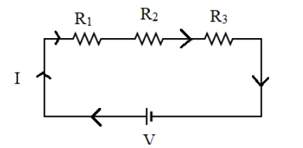
Where, the value of $n$ can be any positive integer which indicates the number of resistors in series.In a series combination, the same amount of current flows through each one of the resistors connected in series while the potential difference across the entire circuit will be equal to the sum of potential drops across each resistor in series. The diagram below represents a circuit which consists of a series combination:

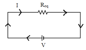
This is a simple circuit in which there are three resistors connected in series with each other. The current through each of them is constant and the total voltage provided by the voltage supply,$V$, is the voltage drop across each resistor. The resistors ${R_1},{R_2},{R_3}$ in series can be replaced by a single resistor of value, say ${R_{eq}}$. Hence, from equation ($1$) since there are three resistors, $n = 3$ we get:
${R_{eq}} = {R_1} + {R_2}$
Hence, the circuit becomes as follows:

(b) When two or more resistances are connected in between two common points they are said to be connected in parallel to each other, that is, when the resistors have a common junction or a separate wire which connects them.
The resistances in parallel equation states that when a number of resistances are connected in parallel then their equivalent, that is, the net resistance will be the sum of the reciprocals of their individual resistances.The resistances in parallel are given by the equation:
$\dfrac{1}{{{R_p}}} = \dfrac{1}{{{R_1}}} + \dfrac{1}{{{R_2}}} + ....\dfrac{1}{{{R_n}}}$ ------($2$)
Where, the value of $n$ can be any positive integer which indicates the number of resistors in series.
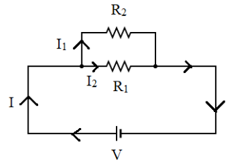
In a parallel combination, the potential difference across the resistors will be equal since the terminals or the junctions connecting them are at the same potential. However, the current will get split at the junction in accordance with Kirchhoff's junction law and the value of current through ${R_1}$ and ${R_2}$ will be different. The diagram below represents a circuit which consists of a parallel combination:

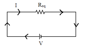
This is a simple circuit in which there are two resistors connected in parallel with each other. The potential difference across the resistors ${R_1}$ and ${R_2}$ is constant while current is split across the junction. The resistors ${R_1}$ and ${R_2}$ in parallel can be replaced by a single resistor of value, say ${R_{eq}}$. We get the value of $n$ to be $2$. From equation ($2$) we get:
$\dfrac{1}{{{R_{eq}}}} = \dfrac{1}{{{R_1}}} + \dfrac{1}{{{R_2}}}$
By taking LCM and solving out we get:
$\dfrac{1}{{{R_{eq}}}} = \dfrac{{{R_1} + {R_2}}}{{{R_1}{R_2}}}$
By taking its reciprocal we get the value of equivalent resistance:
${R_{eq}} = \dfrac{{{R_1}{R_2}}}{{{R_1} + {R_2}}}$
Hence the circuit becomes as follows:

Note: Equivalent resistance is usually larger than the largest individual resistance in the case of series combination and equivalence resistance is usually lesser than the smallest individual resistance in the case of parallel combination. This method is usually used to make calculations simpler and in order to construct a simpler circuit.
Complete step by step answer:
We use a property wherein a combination of two or more resistances which are connected in series or parallel are replaced by a single resistance value and this process is known as reducing of the circuit. The total resistance used to replace the complex circuit of resistors is called the equivalent resistance whose value is what is required to be found by using the concept of resistances in series and parallel.
The advantage of this concept is that currents and voltages across the circuit are independent of the changes in the circuit which means that the reduction of the circuit occurs in such a way that there is no change in the currents and voltages between the terminals of the combination.
(a) A series combination, as the name suggests, is said to be a circuit in which a number of resistors are connected end to end so that they are all connected by a single wire in which all the resistors meant to be in series are attached. The resistances in series equation states that if a number of resistances are connected in series then their equivalent that is the net resistance will be the sum of the individual resistances. This is given by the equation:
${R_s} = {R_1} + {R_2} + {R_3} + .... + {R_n}$ ------($1$)
Where, the value of $n$ can be any positive integer which indicates the number of resistors in series.In a series combination, the same amount of current flows through each one of the resistors connected in series while the potential difference across the entire circuit will be equal to the sum of potential drops across each resistor in series. The diagram below represents a circuit which consists of a series combination:

This is a simple circuit in which there are three resistors connected in series with each other. The current through each of them is constant and the total voltage provided by the voltage supply,$V$, is the voltage drop across each resistor. The resistors ${R_1},{R_2},{R_3}$ in series can be replaced by a single resistor of value, say ${R_{eq}}$. Hence, from equation ($1$) since there are three resistors, $n = 3$ we get:
${R_{eq}} = {R_1} + {R_2}$
Hence, the circuit becomes as follows:

(b) When two or more resistances are connected in between two common points they are said to be connected in parallel to each other, that is, when the resistors have a common junction or a separate wire which connects them.
The resistances in parallel equation states that when a number of resistances are connected in parallel then their equivalent, that is, the net resistance will be the sum of the reciprocals of their individual resistances.The resistances in parallel are given by the equation:
$\dfrac{1}{{{R_p}}} = \dfrac{1}{{{R_1}}} + \dfrac{1}{{{R_2}}} + ....\dfrac{1}{{{R_n}}}$ ------($2$)
Where, the value of $n$ can be any positive integer which indicates the number of resistors in series.
In a parallel combination, the potential difference across the resistors will be equal since the terminals or the junctions connecting them are at the same potential. However, the current will get split at the junction in accordance with Kirchhoff's junction law and the value of current through ${R_1}$ and ${R_2}$ will be different. The diagram below represents a circuit which consists of a parallel combination:

This is a simple circuit in which there are two resistors connected in parallel with each other. The potential difference across the resistors ${R_1}$ and ${R_2}$ is constant while current is split across the junction. The resistors ${R_1}$ and ${R_2}$ in parallel can be replaced by a single resistor of value, say ${R_{eq}}$. We get the value of $n$ to be $2$. From equation ($2$) we get:
$\dfrac{1}{{{R_{eq}}}} = \dfrac{1}{{{R_1}}} + \dfrac{1}{{{R_2}}}$
By taking LCM and solving out we get:
$\dfrac{1}{{{R_{eq}}}} = \dfrac{{{R_1} + {R_2}}}{{{R_1}{R_2}}}$
By taking its reciprocal we get the value of equivalent resistance:
${R_{eq}} = \dfrac{{{R_1}{R_2}}}{{{R_1} + {R_2}}}$
Hence the circuit becomes as follows:

Note: Equivalent resistance is usually larger than the largest individual resistance in the case of series combination and equivalence resistance is usually lesser than the smallest individual resistance in the case of parallel combination. This method is usually used to make calculations simpler and in order to construct a simpler circuit.
Recently Updated Pages
Master Class 10 Computer Science: Engaging Questions & Answers for Success

Master Class 10 General Knowledge: Engaging Questions & Answers for Success

Master Class 10 English: Engaging Questions & Answers for Success

Master Class 10 Social Science: Engaging Questions & Answers for Success

Master Class 10 Maths: Engaging Questions & Answers for Success

Master Class 10 Science: Engaging Questions & Answers for Success

Trending doubts
What is the median of the first 10 natural numbers class 10 maths CBSE

Which women's tennis player has 24 Grand Slam singles titles?

Who is the Brand Ambassador of Incredible India?

Why is there a time difference of about 5 hours between class 10 social science CBSE

Write a letter to the principal requesting him to grant class 10 english CBSE

A moving boat is observed from the top of a 150 m high class 10 maths CBSE


