A galvanometer coil has a resistance $90\Omega $ and full-scale deflection current $10mA$. A $910\Omega $ resistance is connected in series with the galvanometer to make a voltmeter. If the least count of the voltmeter is $0.1V$, the number of divisions on its scale is
A. 90
B. 91
C. 100
D. None
Answer
606.3k+ views
Hint: Design the circuit for the voltmeter and apply the Kirchhoff’s voltage law in the new circuit. For a full deflection current in the galvanometer, find the range of the voltmeter designed. Apply the formula for the number of divisions using the least count and the range to find the answer.
Formula used: Ohm’s law:
$V=iR$
Formula for number of divisions:
$\text{Number of divisions}=\dfrac{\text{Range of the device}}{\text{least count}}$
Complete step-by-step answer:
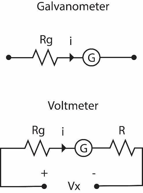
A galvanometer is an instrument which is used to measure the current flowing in a circuit and it is added to the circuit in series. The figure shows the circuit of a galvanometer.
To the galvanometer of resistance ${{R}_{g}}=90\Omega $ an additional resistance of $R=910\Omega $ is added to the circuit to use it as a voltmeter. A voltmeter is a device used to measure voltage across two points in a circuit and it is added in parallel to the circuit.

The voltmeter and the galvanometer work on the principle of Ohm’s law. Which gives us the formula:
$V=iR$
The following figure shows the circuit for the voltmeter we built. It measures the voltage across the ends A and B. Applying KVL (Kirchhoff’s voltage law) in the circuit, we get the expression:
${{V}_{x}}=i(R+{{R}_{g}})=1000i$
Here $i$ is the current that the galvanometer measures. Since, the galvanometer can only show a deflection up to 10mA, the maximum that our voltmeter can show will be $1000\times 10\times {{10}^{-3}}V=10V$.
Since the least count of the voltmeter is $0.1V$, the number of divisions can be given by the formula:
$\begin{align}
& \text{Number of divisions}=\dfrac{\text{Range of the device}}{\text{least count}} \\
& \Rightarrow \text{Number of divisions}=\dfrac{10V}{0.1V}=100 \\
\end{align}$
Therefore, the correct answer is option C. 100.
Note: Students can get confused how to design the circuit for the galvanometer and the voltmeter. Note that galvanometer is added to the circuit in series with small value of resistance to ensure the original value of the voltage difference in the circuit varies negligibly. Similarly, voltmeter is added in parallel to the circuit. The resistance in the voltmeter is high to ensure only a small current passes through the voltmeter branch, varying the original current in the circuit negligibly.
Formula used: Ohm’s law:
$V=iR$
Formula for number of divisions:
$\text{Number of divisions}=\dfrac{\text{Range of the device}}{\text{least count}}$
Complete step-by-step answer:
A galvanometer is an instrument which is used to measure the current flowing in a circuit and it is added to the circuit in series. The figure shows the circuit of a galvanometer.
To the galvanometer of resistance ${{R}_{g}}=90\Omega $ an additional resistance of $R=910\Omega $ is added to the circuit to use it as a voltmeter. A voltmeter is a device used to measure voltage across two points in a circuit and it is added in parallel to the circuit.

The voltmeter and the galvanometer work on the principle of Ohm’s law. Which gives us the formula:
$V=iR$
The following figure shows the circuit for the voltmeter we built. It measures the voltage across the ends A and B. Applying KVL (Kirchhoff’s voltage law) in the circuit, we get the expression:
${{V}_{x}}=i(R+{{R}_{g}})=1000i$
Here $i$ is the current that the galvanometer measures. Since, the galvanometer can only show a deflection up to 10mA, the maximum that our voltmeter can show will be $1000\times 10\times {{10}^{-3}}V=10V$.
Since the least count of the voltmeter is $0.1V$, the number of divisions can be given by the formula:
$\begin{align}
& \text{Number of divisions}=\dfrac{\text{Range of the device}}{\text{least count}} \\
& \Rightarrow \text{Number of divisions}=\dfrac{10V}{0.1V}=100 \\
\end{align}$
Therefore, the correct answer is option C. 100.
Note: Students can get confused how to design the circuit for the galvanometer and the voltmeter. Note that galvanometer is added to the circuit in series with small value of resistance to ensure the original value of the voltage difference in the circuit varies negligibly. Similarly, voltmeter is added in parallel to the circuit. The resistance in the voltmeter is high to ensure only a small current passes through the voltmeter branch, varying the original current in the circuit negligibly.
Recently Updated Pages
Master Class 11 Computer Science: Engaging Questions & Answers for Success

Master Class 11 Business Studies: Engaging Questions & Answers for Success

Master Class 11 Economics: Engaging Questions & Answers for Success

Master Class 11 English: Engaging Questions & Answers for Success

Master Class 11 Maths: Engaging Questions & Answers for Success

Master Class 11 Biology: Engaging Questions & Answers for Success

Trending doubts
One Metric ton is equal to kg A 10000 B 1000 C 100 class 11 physics CBSE

There are 720 permutations of the digits 1 2 3 4 5 class 11 maths CBSE

Discuss the various forms of bacteria class 11 biology CBSE

Draw a diagram of a plant cell and label at least eight class 11 biology CBSE

State the laws of reflection of light

Explain zero factorial class 11 maths CBSE


