


A generator contains a coil that spins to produce an electric current. How is energy transformed by using a generator?
Answer
541.5k+ views
Hint: As the name suggests, an (electric) generator produces electric currents by some form of energy conversion. Think of the different parts of the generator and how they contribute towards producing current. In other words, use the principle of electromagnetic induction for a coil rotating in a constant magnetic field to arrive at your description. Do not forget to account for directional changes in the induced current.
Complete answer:
Let us begin by understanding what a generator is.
A generator is a mechanical rotating device that converts mechanical energy to electrical energy and is based on the principle of electromagnetic induction.
Now, electromagnetic induction is the process by which we produce an electromotive force (which is basically a voltage) across a conductor by relative motion between the coil and the magnetic field. In our case, we consider the process of induction where we rotate the conductor in a constant magnetic field, i.e., the magnetic field direction does not change.
Here, we shall look at an AC generator.
An AC generator works on the principle of electromagnetic induction where current is induced in the coil that is placed in a magnetic field.
Let us first look at the structure of the AC generator from the diagram.
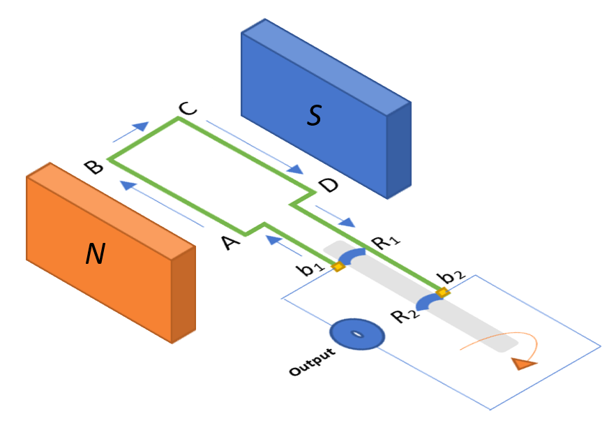
It consists of a rectangular coil ABCD that is placed between the two poles of a permanent magnet which is our source of a constant magnetic field directed from North to South. The ends of the coil are connected to the rings $R_1$ and $R_2$. These rings are slid into and fixed over a rotating axle (in grey) that we use to mechanically move the coil. The inner side of these rings are insulated. In stationary contact with these rings are the conducting brushes $b_1$ and $b_2$ respectively. The brushes are used to conduct the current to the external circuit, which consists of an output, which we shall assume here to be a galvanometer that produces a rotary deflection in response to the magnitude and direction of the current flowing through a coil in a constant magnetic field.
Now we can look at the working of an AC generator.
When the axle is moved in the clockwise direction, i.e., when the side AB moves up and CD moves down with respect to the constant magnetic field, using Fleming’s left-hand rule we can deduce that the induced currents are set up from A to B and C to D. Therefore, the flow of induced current is in the direction of ABCD. This means that the current in the external circuit flows from $b_2$ to $b_1$. After one half-rotation, the side CD moves up and side AB moves down. Consequently, the flow of induced current changes and the direction of flow now becomes DCBA, and the external circuit sees current flowing from $b_1$ to $b_2$. This concludes that after every half rotation the polarity of the induced current changes, and this change can be evidently seen in a galvanometer connected to the external circuit. Thus, current is produced from the rotation of the coil, and since it is alternating current, we call this device an AC generator.
Note:
In general, there are in fact two types of generators:
An AC generator: The electrical current (alternating current) produced reverses direction periodically
A DC generator: Also known as a dynamo, the current (direct current) produced flows in only one direction
Here, we looked at the more efficient and reliable system, which is the AC generator. However, DC generators are used to power very large electric motors like subway systems but require more maintenance.
Also, an AC generator can be converted into a DC generator by using a split-ring commutator, which basically reverses the current direction after every half rotation. Therefore, the split-ring commutator restores the desired direction of the current by consistently countering the change in the induced current direction for alternate half-rotations.
Complete answer:
Let us begin by understanding what a generator is.
A generator is a mechanical rotating device that converts mechanical energy to electrical energy and is based on the principle of electromagnetic induction.
Now, electromagnetic induction is the process by which we produce an electromotive force (which is basically a voltage) across a conductor by relative motion between the coil and the magnetic field. In our case, we consider the process of induction where we rotate the conductor in a constant magnetic field, i.e., the magnetic field direction does not change.
Here, we shall look at an AC generator.
An AC generator works on the principle of electromagnetic induction where current is induced in the coil that is placed in a magnetic field.
Let us first look at the structure of the AC generator from the diagram.
It consists of a rectangular coil ABCD that is placed between the two poles of a permanent magnet which is our source of a constant magnetic field directed from North to South. The ends of the coil are connected to the rings $R_1$ and $R_2$. These rings are slid into and fixed over a rotating axle (in grey) that we use to mechanically move the coil. The inner side of these rings are insulated. In stationary contact with these rings are the conducting brushes $b_1$ and $b_2$ respectively. The brushes are used to conduct the current to the external circuit, which consists of an output, which we shall assume here to be a galvanometer that produces a rotary deflection in response to the magnitude and direction of the current flowing through a coil in a constant magnetic field.
Now we can look at the working of an AC generator.
When the axle is moved in the clockwise direction, i.e., when the side AB moves up and CD moves down with respect to the constant magnetic field, using Fleming’s left-hand rule we can deduce that the induced currents are set up from A to B and C to D. Therefore, the flow of induced current is in the direction of ABCD. This means that the current in the external circuit flows from $b_2$ to $b_1$. After one half-rotation, the side CD moves up and side AB moves down. Consequently, the flow of induced current changes and the direction of flow now becomes DCBA, and the external circuit sees current flowing from $b_1$ to $b_2$. This concludes that after every half rotation the polarity of the induced current changes, and this change can be evidently seen in a galvanometer connected to the external circuit. Thus, current is produced from the rotation of the coil, and since it is alternating current, we call this device an AC generator.
Note:
In general, there are in fact two types of generators:
An AC generator: The electrical current (alternating current) produced reverses direction periodically
A DC generator: Also known as a dynamo, the current (direct current) produced flows in only one direction
Here, we looked at the more efficient and reliable system, which is the AC generator. However, DC generators are used to power very large electric motors like subway systems but require more maintenance.
Also, an AC generator can be converted into a DC generator by using a split-ring commutator, which basically reverses the current direction after every half rotation. Therefore, the split-ring commutator restores the desired direction of the current by consistently countering the change in the induced current direction for alternate half-rotations.
Recently Updated Pages
Master Class 11 Computer Science: Engaging Questions & Answers for Success
Master Class 11 Business Studies: Engaging Questions & Answers for Success
Master Class 11 Economics: Engaging Questions & Answers for Success
Master Class 11 English: Engaging Questions & Answers for Success
Master Class 11 Maths: Engaging Questions & Answers for Success
Master Class 11 Biology: Engaging Questions & Answers for Success
Trending doubts
One Metric ton is equal to kg A 10000 B 1000 C 100 class 11 physics CBSE
There are 720 permutations of the digits 1 2 3 4 5 class 11 maths CBSE
Discuss the various forms of bacteria class 11 biology CBSE
Draw a diagram of a plant cell and label at least eight class 11 biology CBSE
State the laws of reflection of light
Explain zero factorial class 11 maths CBSE