


Explain with the help of a circuit diagram, the working of a p-n junction diode as a half wave rectifier.
Answer
233.1k+ views
Hint: A p-n junction diode is the type of diode formed after fusing p-type and n-type semiconductor creating a potential barrier voltage across the diode junction. A half wave rectifier uses the principle of p-n junction . The rectifiers are used to convert AC to DC voltage.
Complete step by step solution:

The above diagram is a p-n junction diode, where one end is doped with p type and n type and is connected to a conductive terminal. The depletion region in the junction consists of holes and free electrons and p type of depletion is negatively charged due to attraction of electron while the n type of depletion region is positively charged due to presence of holes.
A rectifier is one of the basic electronics devices , the device is commonly used to alternate AC to DC voltage. On the basis of period of conduction it can be of two types ie Half wave rectifier and Full wave rectifier.
Principle of Half wave rectifier:
Half wave rectifier works on the principle of a p-n junction diode , to convert AC to DC voltage. P-n junction diode is connected serially with the rectifier circuit .
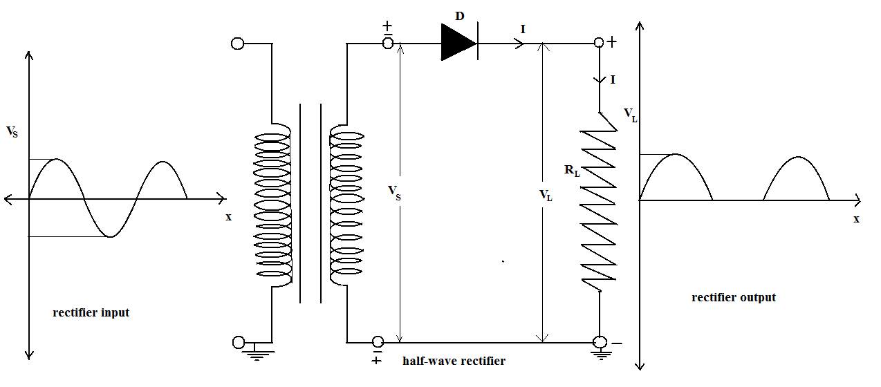
The above diagram illustrates the working of a half wave rectifier , the initial input is Alternating current, the step down transformer receives the input voltage and transfers it finally to the load resistor and to the diode.
During the positive half of the cycle , the diode operates as forward biasing and during the negative half cycle , the diode starts operating as reverse biasing.
While there is a positive cycle of diode , the output is positive and significant but during the negative cycle of diode, the output becomes negative and insignificant. This process is called the half wave rectification.
The characteristics of half-wave rectifier are:
1. PIV( Peak Inverse voltage): The peak Inverse voltage is the peak voltage a diode has to maintain during the reverse biasing condition due to no load situation at the rectifier. During the negative cycle of the half wave rectifier , there is no flow of current through the load and so an entire voltage surface at the diode.
2. Regulation: Regulation of half wave rectifiers is defined as difference between no load voltage to full load voltage in comparison to full load voltage.
3. Efficiency: The efficiency of the half wave rectifier is given by the ratio of input AC to the DC output.
4. Ripple factor: It refers to the amount of AC remaining in DC output. If ripple factor is less it represents a high rectifier performance. The ripple factor for a half wave rectifier is usually 1.21.
5. Transformer Utilization factor (TUF): Transformer Utilization factor is the ratio of AC power delivered to the load and transformer secondary AC rating . For a half wave rectifier the TUF is usually 0.287.
Note: A half wave rectifier is a simple and easy device but it has its disadvantages like it generates harmonics and there are usually more amount of ripple content. A single diode is used for a single phase rectifier and 3 diodes for three phase rectifier.
Complete step by step solution:
The above diagram is a p-n junction diode, where one end is doped with p type and n type and is connected to a conductive terminal. The depletion region in the junction consists of holes and free electrons and p type of depletion is negatively charged due to attraction of electron while the n type of depletion region is positively charged due to presence of holes.
A rectifier is one of the basic electronics devices , the device is commonly used to alternate AC to DC voltage. On the basis of period of conduction it can be of two types ie Half wave rectifier and Full wave rectifier.
Principle of Half wave rectifier:
Half wave rectifier works on the principle of a p-n junction diode , to convert AC to DC voltage. P-n junction diode is connected serially with the rectifier circuit .
The above diagram illustrates the working of a half wave rectifier , the initial input is Alternating current, the step down transformer receives the input voltage and transfers it finally to the load resistor and to the diode.
During the positive half of the cycle , the diode operates as forward biasing and during the negative half cycle , the diode starts operating as reverse biasing.
While there is a positive cycle of diode , the output is positive and significant but during the negative cycle of diode, the output becomes negative and insignificant. This process is called the half wave rectification.
The characteristics of half-wave rectifier are:
1. PIV( Peak Inverse voltage): The peak Inverse voltage is the peak voltage a diode has to maintain during the reverse biasing condition due to no load situation at the rectifier. During the negative cycle of the half wave rectifier , there is no flow of current through the load and so an entire voltage surface at the diode.
2. Regulation: Regulation of half wave rectifiers is defined as difference between no load voltage to full load voltage in comparison to full load voltage.
3. Efficiency: The efficiency of the half wave rectifier is given by the ratio of input AC to the DC output.
4. Ripple factor: It refers to the amount of AC remaining in DC output. If ripple factor is less it represents a high rectifier performance. The ripple factor for a half wave rectifier is usually 1.21.
5. Transformer Utilization factor (TUF): Transformer Utilization factor is the ratio of AC power delivered to the load and transformer secondary AC rating . For a half wave rectifier the TUF is usually 0.287.
Note: A half wave rectifier is a simple and easy device but it has its disadvantages like it generates harmonics and there are usually more amount of ripple content. A single diode is used for a single phase rectifier and 3 diodes for three phase rectifier.
Recently Updated Pages
JEE Main 2023 April 6 Shift 1 Question Paper with Answer Key
JEE Main 2023 April 6 Shift 2 Question Paper with Answer Key
JEE Main 2023 (January 31 Evening Shift) Question Paper with Solutions [PDF]
JEE Main 2023 January 30 Shift 2 Question Paper with Answer Key
JEE Main 2023 January 25 Shift 1 Question Paper with Answer Key
JEE Main 2023 January 24 Shift 2 Question Paper with Answer Key
Trending doubts
JEE Main 2026: Session 2 Registration Open, City Intimation Slip, Exam Dates, Syllabus & Eligibility
JEE Main 2026 Application Login: Direct Link, Registration, Form Fill, and Steps
JEE Main Marking Scheme 2026- Paper-Wise Marks Distribution and Negative Marking Details
Understanding the Angle of Deviation in a Prism
Hybridisation in Chemistry – Concept, Types & Applications
How to Convert a Galvanometer into an Ammeter or Voltmeter
Other Pages
JEE Advanced Marks vs Ranks 2025: Understanding Category-wise Qualifying Marks and Previous Year Cut-offs
Dual Nature of Radiation and Matter Class 12 Physics Chapter 11 CBSE Notes - 2025-26
Understanding Uniform Acceleration in Physics
Understanding the Electric Field of a Uniformly Charged Ring
JEE Advanced Weightage 2025 Chapter-Wise for Physics, Maths and Chemistry
Derivation of Equation of Trajectory Explained for Students