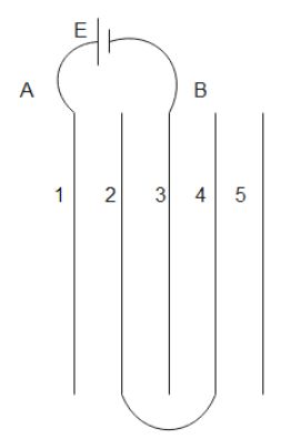
Five conducting parallel plates having area A and separation between them d, are placed as shown in the figure. Plate number 2 and 4 are connected with wire and between A and B, a cell of emf E is connected. A charge flown through the cell is.

A. $\dfrac{3}{4}\dfrac{{{\varepsilon _0}AE}}{d}$
B. $\dfrac{2}{3}\dfrac{{{\varepsilon _0}AE}}{d}$
C. $\dfrac{{4{\varepsilon _0}AE}}{d}$
D. $\dfrac{{{\varepsilon _0}AE}}{{2d}}$

Answer
573.3k+ views
Hint: Capacitor is a device which is used to store the charge. The charge stored in the capacitor depends on the potential difference applied across them and also depends on the capacitance of the capacitor. We have different formulas to find out effective capacitance when they are connected in series or parallel.
Formula used:
$\eqalign{
& \dfrac{1}{{{C_S}}} = \dfrac{1}{{{C_1}}} + \dfrac{1}{{{C_2}}} + \dfrac{1}{{{C_3}}} + \dfrac{1}{{{C_4}}}{\text{ }}......... \cr
& {C_P} = {C_1} + {C_2} + {C_3} + {C_4}{\text{ }}........... \cr} $
Complete answer:
Generally when there are more than one capacitors, we can connect them in series or we can connect them in parallel.
In case of series connection the current flowing through the circuit will be the same which means that the charge stored on the every capacitor will be the same as the charge is nothing but the current flowing in a given time.
In case of parallel connection the voltage across all the capacitors will be the same.
In series connection charge will be same and voltage will be divided across the capacitors whereas in parallel connection voltage will be same and charge will be divided across the capacitors.
Effective capacitance for capacitors in series connection is
$\dfrac{1}{{{C_S}}} = \dfrac{1}{{{C_1}}} + \dfrac{1}{{{C_2}}} + \dfrac{1}{{{C_3}}} + \dfrac{1}{{{C_4}}}{\text{ }}.........$
Effective capacitance for capacitors in parallel connection is
${C_P} = {C_1} + {C_2} + {C_3} + {C_4}{\text{ }}...........$
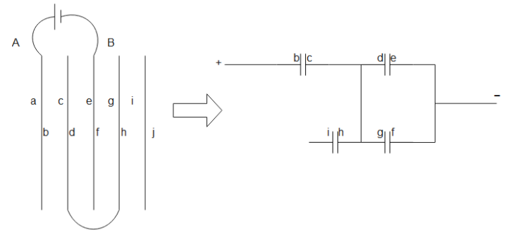
The given circuit in the question can be modified further as below

From the above diagram we can clearly see that only three capacitors are effective and the capacitor having plates i and h is ineffective. Let capacitance of each capacitor is C
Last two capacitors in the diagram are in parallel so the effective capacitance of them is
${C_P} = {C_1} + {C_2} + {C_3} + {C_4}{\text{ }}...........$
${C_P} = C + C = 2C$
Now 2C and remaining C are in series. So their effective capacitance is
$\dfrac{1}{{{C_S}}} = \dfrac{1}{{{C_1}}} + \dfrac{1}{{{C_2}}} + \dfrac{1}{{{C_3}}} + \dfrac{1}{{{C_4}}}{\text{ }}.........$
$\eqalign{
& \Rightarrow \dfrac{1}{{{C_S}}} = \dfrac{1}{{2C}} + \dfrac{1}{C} \cr
& \therefore {C_S} = \dfrac{{2C}}{3} \cr} $
We know that
$\eqalign{
& C = \dfrac{{{\varepsilon _0}A}}{d} \cr
& \Rightarrow Q = CV \cr
& \therefore Q = \dfrac{2}{3}\dfrac{{{\varepsilon _0}AE}}{d} \cr} $
Where V is the emf of the cell which is E here and A is the area of plates and ‘d’ is distance between plates.
Hence option B is the answer.
Note:
The formulas which we have for the case of finding effective capacitance of parallel and series connection of capacitors will be exactly opposite to the case of finding effective resistance of parallel and series connection of resistors. All the plates given are identical plates or else we will have different capacitances.
Formula used:
$\eqalign{
& \dfrac{1}{{{C_S}}} = \dfrac{1}{{{C_1}}} + \dfrac{1}{{{C_2}}} + \dfrac{1}{{{C_3}}} + \dfrac{1}{{{C_4}}}{\text{ }}......... \cr
& {C_P} = {C_1} + {C_2} + {C_3} + {C_4}{\text{ }}........... \cr} $
Complete answer:
Generally when there are more than one capacitors, we can connect them in series or we can connect them in parallel.
In case of series connection the current flowing through the circuit will be the same which means that the charge stored on the every capacitor will be the same as the charge is nothing but the current flowing in a given time.
In case of parallel connection the voltage across all the capacitors will be the same.
In series connection charge will be same and voltage will be divided across the capacitors whereas in parallel connection voltage will be same and charge will be divided across the capacitors.
Effective capacitance for capacitors in series connection is
$\dfrac{1}{{{C_S}}} = \dfrac{1}{{{C_1}}} + \dfrac{1}{{{C_2}}} + \dfrac{1}{{{C_3}}} + \dfrac{1}{{{C_4}}}{\text{ }}.........$
Effective capacitance for capacitors in parallel connection is
${C_P} = {C_1} + {C_2} + {C_3} + {C_4}{\text{ }}...........$
The given circuit in the question can be modified further as below

From the above diagram we can clearly see that only three capacitors are effective and the capacitor having plates i and h is ineffective. Let capacitance of each capacitor is C
Last two capacitors in the diagram are in parallel so the effective capacitance of them is
${C_P} = {C_1} + {C_2} + {C_3} + {C_4}{\text{ }}...........$
${C_P} = C + C = 2C$
Now 2C and remaining C are in series. So their effective capacitance is
$\dfrac{1}{{{C_S}}} = \dfrac{1}{{{C_1}}} + \dfrac{1}{{{C_2}}} + \dfrac{1}{{{C_3}}} + \dfrac{1}{{{C_4}}}{\text{ }}.........$
$\eqalign{
& \Rightarrow \dfrac{1}{{{C_S}}} = \dfrac{1}{{2C}} + \dfrac{1}{C} \cr
& \therefore {C_S} = \dfrac{{2C}}{3} \cr} $
We know that
$\eqalign{
& C = \dfrac{{{\varepsilon _0}A}}{d} \cr
& \Rightarrow Q = CV \cr
& \therefore Q = \dfrac{2}{3}\dfrac{{{\varepsilon _0}AE}}{d} \cr} $
Where V is the emf of the cell which is E here and A is the area of plates and ‘d’ is distance between plates.
Hence option B is the answer.
Note:
The formulas which we have for the case of finding effective capacitance of parallel and series connection of capacitors will be exactly opposite to the case of finding effective resistance of parallel and series connection of resistors. All the plates given are identical plates or else we will have different capacitances.
Recently Updated Pages
Master Class 12 Economics: Engaging Questions & Answers for Success

Master Class 12 Physics: Engaging Questions & Answers for Success

Master Class 12 English: Engaging Questions & Answers for Success

Master Class 12 Social Science: Engaging Questions & Answers for Success

Master Class 12 Maths: Engaging Questions & Answers for Success

Master Class 12 Business Studies: Engaging Questions & Answers for Success

Trending doubts
Which are the Top 10 Largest Countries of the World?

What are the major means of transport Explain each class 12 social science CBSE

Draw a labelled sketch of the human eye class 12 physics CBSE

Why cannot DNA pass through cell membranes class 12 biology CBSE

Differentiate between insitu conservation and exsitu class 12 biology CBSE

Draw a neat and well labeled diagram of TS of ovary class 12 biology CBSE


