


In LCR circuit, the power factor at resonance is
A. Less than one
B. Greater than one
C. Unity
D. Can’t predict
Answer
596.1k+ views
Hint: For an RLC circuit in series, consider the same current flowing through the circuit and find out the voltages across the inductor, capacitor and resistor. Apply the condition of resonance to find the value of the phase difference in the voltage and current. Then apply it in the power factor formula.
Formula used: The condition for resonance in an RLC series circuit:
$\begin{align}
& {{X}_{C}}={{X}_{L}} \\
& \dfrac{1}{\omega C}=\omega L \\
& \omega =\dfrac{1}{\sqrt{LC}} \\
\end{align}$
Formula for real power:
\[P={{I}_{rms}}{{V}_{rms}}\cos (\Phi )\]
Complete step-by-step answer:
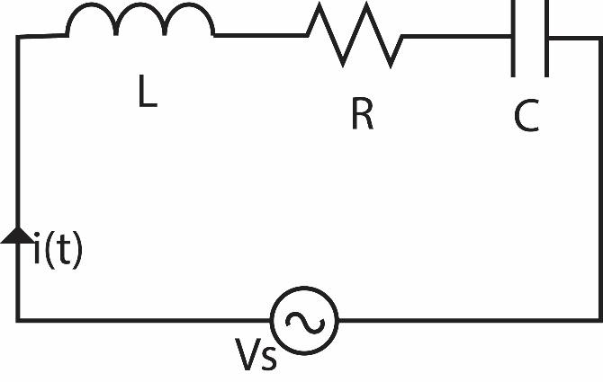
For the LCR circuit given in the figure, when the input is a sinusoidal wave, the following analysis can be proposed.
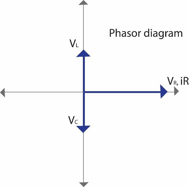
The voltage across the resistor remains in phase with the current in the circuit. The voltage across the inductor leads the current by $\dfrac{\pi }{2}$. Whereas, the voltage across the capacitor lags the current by $\dfrac{\pi }{2}$. Since the components are connected in series, the same current $i$ flows through all the elements. Therefore, the following phasor diagram can be drawn.
Where, for capacitor:
$\begin{align}
& {{V}_{C}}=-j{{X}_{C}}i(t) \\
& {{X}_{C}}=\dfrac{1}{\omega C} \\
\end{align}$
For inductor:
$\begin{align}
& {{V}_{L}}=j{{X}_{L}}i(t) \\
& {{X}_{L}}=\omega L \\
\end{align}$
For resistor:
$\begin{align}
& {{V}_{R}}=i(t)R \\
& {{X}_{R}}=R \\
\end{align}$
For the circuit to be resonant,
$\begin{align}
& {{X}_{C}}={{X}_{L}} \\
& \dfrac{1}{\omega C}=\omega L \\
& \omega =\dfrac{1}{\sqrt{LC}} \\
\end{align}$
That is the net voltage and the current are in the same phase.
Suppose the instantaneous current through a circuit is $i(t)={{I}_{\max }}\sin (\omega t)$ and the net instantaneous voltage across the components is $v(t)={{V}_{\max }}\sin (\omega t+\Phi )$, then the real power is given by:
\[P={{I}_{rms}}{{V}_{rms}}\cos (\Phi )\]
Where, $\cos (\Phi )$ is the power factor.
Power factor is defined as the ratio of the actual electric power dissipated by AC circuit to the product of the rms (root mean square) voltage and current. The non-useful work is the contribution of the reactance.
Since, for a circuit operating at resonance, the phase difference between voltage and current is zero. Therefore, the power factor becomes $\cos (0)=1$.
The answer to this question is 1.
Note: At resonance in a circuit, the frequency of the source helps to balance the reactive elements in the circuit. The capacitive and the inductive load balance each other out. And the resultant impedance is only resistive in nature. Thus, all the work done is the real work. Hence, by the definition of power factor, it becomes 1.
Formula used: The condition for resonance in an RLC series circuit:
$\begin{align}
& {{X}_{C}}={{X}_{L}} \\
& \dfrac{1}{\omega C}=\omega L \\
& \omega =\dfrac{1}{\sqrt{LC}} \\
\end{align}$
Formula for real power:
\[P={{I}_{rms}}{{V}_{rms}}\cos (\Phi )\]
Complete step-by-step answer:
For the LCR circuit given in the figure, when the input is a sinusoidal wave, the following analysis can be proposed.
The voltage across the resistor remains in phase with the current in the circuit. The voltage across the inductor leads the current by $\dfrac{\pi }{2}$. Whereas, the voltage across the capacitor lags the current by $\dfrac{\pi }{2}$. Since the components are connected in series, the same current $i$ flows through all the elements. Therefore, the following phasor diagram can be drawn.
Where, for capacitor:
$\begin{align}
& {{V}_{C}}=-j{{X}_{C}}i(t) \\
& {{X}_{C}}=\dfrac{1}{\omega C} \\
\end{align}$
For inductor:
$\begin{align}
& {{V}_{L}}=j{{X}_{L}}i(t) \\
& {{X}_{L}}=\omega L \\
\end{align}$
For resistor:
$\begin{align}
& {{V}_{R}}=i(t)R \\
& {{X}_{R}}=R \\
\end{align}$
For the circuit to be resonant,
$\begin{align}
& {{X}_{C}}={{X}_{L}} \\
& \dfrac{1}{\omega C}=\omega L \\
& \omega =\dfrac{1}{\sqrt{LC}} \\
\end{align}$
That is the net voltage and the current are in the same phase.
Suppose the instantaneous current through a circuit is $i(t)={{I}_{\max }}\sin (\omega t)$ and the net instantaneous voltage across the components is $v(t)={{V}_{\max }}\sin (\omega t+\Phi )$, then the real power is given by:
\[P={{I}_{rms}}{{V}_{rms}}\cos (\Phi )\]
Where, $\cos (\Phi )$ is the power factor.
Power factor is defined as the ratio of the actual electric power dissipated by AC circuit to the product of the rms (root mean square) voltage and current. The non-useful work is the contribution of the reactance.
Since, for a circuit operating at resonance, the phase difference between voltage and current is zero. Therefore, the power factor becomes $\cos (0)=1$.
The answer to this question is 1.
Note: At resonance in a circuit, the frequency of the source helps to balance the reactive elements in the circuit. The capacitive and the inductive load balance each other out. And the resultant impedance is only resistive in nature. Thus, all the work done is the real work. Hence, by the definition of power factor, it becomes 1.
Recently Updated Pages
Master Class 11 Computer Science: Engaging Questions & Answers for Success
Master Class 11 Business Studies: Engaging Questions & Answers for Success
Master Class 11 Economics: Engaging Questions & Answers for Success
Master Class 11 English: Engaging Questions & Answers for Success
Master Class 11 Maths: Engaging Questions & Answers for Success
Master Class 11 Biology: Engaging Questions & Answers for Success
Trending doubts
One Metric ton is equal to kg A 10000 B 1000 C 100 class 11 physics CBSE
There are 720 permutations of the digits 1 2 3 4 5 class 11 maths CBSE
Discuss the various forms of bacteria class 11 biology CBSE
Draw a diagram of a plant cell and label at least eight class 11 biology CBSE
State the laws of reflection of light
Explain zero factorial class 11 maths CBSE