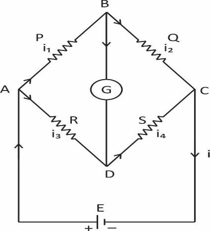
Obtain the condition for bridge balance in Wheatstone’s bridge.
Answer
587.4k+ views
Hint: The bridge is in the unbalanced condition where current flows through the galvanometer. Wheatstone bridge along with an operational amplifier is used to measure the physical parameters like temperature, strain, light, etc.
Complete step by step solution:

Wheatstone’s bridge is an important application of Kirchoff’s.
Wheatstone bridge consist of resistances P, Q, R and S connected to form a closed path A cell of EMF (E) is connected between point A and C. The current I from the cell is divided into \[{I_1},\,\,{I_2},\,\,{I_3}\] and \[{I_4}\] across the four branches. The current through the galvanometer is G.
Applying Kirchoff’s current law to junction B,
\[{I_1} - {I_g} - {I_3} = 0\] …. (1)
Applying Kirchoff’s current law to junction D,
\[{I_2} + {I_g} - {I_4} = 0\] … (2)
Applying Kirchoff’s voltage law to closed path ABDA
\[{I_1}P + {I_g}G - {I_2}R = 0\] … (3)
Applying Kirchoff’s voltage law to closed path ABCDA
\[{I_1}P + {I_3}Q - {I_4}S - {I_2}R = 0\] ... (4)
When the galvanometer shows zero deflection points, B and D are at same potential and \[{I_g} = 0\]. Substituting \[{I_g} = 0\] in equation (1), (2) and (3), we have
\[{I_1} = {I_3}\] …(5)
\[{I_2} = {I_4}\] …(6)
\[{I_1}P = {I_2}R\] …(7)
Substituting the values of (5) and (6) in equation (4)
\[{I_1}P + {I_1}Q - {I_2}S - {I_2}R = 0\]
\[{I_1}\left( {P + Q} \right) = {I_2}\left( {R + S} \right)\]
Dividing (8) by (7), we have
\[\dfrac{{{I_1}\left( {P + Q} \right)}}{{{I_1}\,\,P}} = \dfrac{{{I_2}\left( {R + S} \right)}}{{{I_2}R}}\]
\[\therefore \,\,\,\,\dfrac{{P + Q}}{P} = \dfrac{{R + S}}{R}\]
\[ = I + \dfrac{Q}{P} = I + \dfrac{S}{R}\]
\[\therefore \dfrac{Q}{P} = \dfrac{S}{R}\,\,\,or\,\,\,\dfrac{P}{Q} = \dfrac{R}{S}\]
Note: While solving such problems we have to keep in mind few things otherwise our answer will come wrong. We have to see how many batteries are there in the circuit. If there is only one battery in a loop then it is okay but if there are more than one we have to consider individual currents and one voltage and another will be considered and will be added or subtracted depending upon the polarities alignment of the given batteries.
Complete step by step solution:

Wheatstone’s bridge is an important application of Kirchoff’s.
Wheatstone bridge consist of resistances P, Q, R and S connected to form a closed path A cell of EMF (E) is connected between point A and C. The current I from the cell is divided into \[{I_1},\,\,{I_2},\,\,{I_3}\] and \[{I_4}\] across the four branches. The current through the galvanometer is G.
Applying Kirchoff’s current law to junction B,
\[{I_1} - {I_g} - {I_3} = 0\] …. (1)
Applying Kirchoff’s current law to junction D,
\[{I_2} + {I_g} - {I_4} = 0\] … (2)
Applying Kirchoff’s voltage law to closed path ABDA
\[{I_1}P + {I_g}G - {I_2}R = 0\] … (3)
Applying Kirchoff’s voltage law to closed path ABCDA
\[{I_1}P + {I_3}Q - {I_4}S - {I_2}R = 0\] ... (4)
When the galvanometer shows zero deflection points, B and D are at same potential and \[{I_g} = 0\]. Substituting \[{I_g} = 0\] in equation (1), (2) and (3), we have
\[{I_1} = {I_3}\] …(5)
\[{I_2} = {I_4}\] …(6)
\[{I_1}P = {I_2}R\] …(7)
Substituting the values of (5) and (6) in equation (4)
\[{I_1}P + {I_1}Q - {I_2}S - {I_2}R = 0\]
\[{I_1}\left( {P + Q} \right) = {I_2}\left( {R + S} \right)\]
Dividing (8) by (7), we have
\[\dfrac{{{I_1}\left( {P + Q} \right)}}{{{I_1}\,\,P}} = \dfrac{{{I_2}\left( {R + S} \right)}}{{{I_2}R}}\]
\[\therefore \,\,\,\,\dfrac{{P + Q}}{P} = \dfrac{{R + S}}{R}\]
\[ = I + \dfrac{Q}{P} = I + \dfrac{S}{R}\]
\[\therefore \dfrac{Q}{P} = \dfrac{S}{R}\,\,\,or\,\,\,\dfrac{P}{Q} = \dfrac{R}{S}\]
Note: While solving such problems we have to keep in mind few things otherwise our answer will come wrong. We have to see how many batteries are there in the circuit. If there is only one battery in a loop then it is okay but if there are more than one we have to consider individual currents and one voltage and another will be considered and will be added or subtracted depending upon the polarities alignment of the given batteries.
Recently Updated Pages
Master Class 11 Computer Science: Engaging Questions & Answers for Success

Master Class 11 Business Studies: Engaging Questions & Answers for Success

Master Class 11 Economics: Engaging Questions & Answers for Success

Master Class 11 English: Engaging Questions & Answers for Success

Master Class 11 Maths: Engaging Questions & Answers for Success

Master Class 11 Biology: Engaging Questions & Answers for Success

Trending doubts
One Metric ton is equal to kg A 10000 B 1000 C 100 class 11 physics CBSE

There are 720 permutations of the digits 1 2 3 4 5 class 11 maths CBSE

Discuss the various forms of bacteria class 11 biology CBSE

Draw a diagram of a plant cell and label at least eight class 11 biology CBSE

State the laws of reflection of light

10 examples of friction in our daily life


