


The turn’s ratio of the transformer used in a bridge rectifier is 10 : 1. The primary is connected to $220{\text{V}}$ , $50{\text{Hz}}$ power mains. Find the output DC voltage, PIV of the diode and ripple frequency under no-load condition assuming the voltage drop across the diode to be zero.
Answer
578.4k+ views
Hint:Here the output voltage of the transformer will be the input to the bridge rectifier. This suggests that the line voltage of the secondary coil of the given transformer will be the input to the bridge rectifier. The turn’s ratio is proportional to the voltage ratio of the transformer. Ripple frequency refers to the frequency of the residual ac voltage present in the rectified output. The PIV rating refers to the maximum voltage that the diodes in the given bridge rectifier can withstand without breaking down. For the given bridge rectifier, PIV will be the peak voltage of the secondary coil.
Formulas used:
-The dc voltage under the no-load condition for a bridge rectifier is given by, ${V_{dc}} = \dfrac{{2{v_m}}}{\pi }$ where ${v_m}$ is the maximum value of the input voltage.
-The PIV rating of the diode in a bridge rectifier is given by $PIV = {v_m}$ where ${v_m}$ is the maximum value of the input voltage of the rectifier.
-The ripple frequency of a bridge rectifier is given by, ${\text{ripple frequency}} = 2f$ where $f$ is the frequency of the input voltage.
-The voltage across the secondary coil of a transformer is given by, ${V_s} = \left( {\dfrac{{{N_s}}}{{{N_p}}}} \right){V_p}$
Complete step by step answer.
Step 1: Sketch a diagram representing the arrangement of the transformer and the bridge rectifier and list the parameters given in the question.
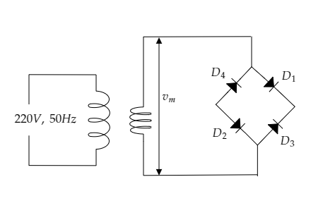
In the above figure, a step-down transformer is connected to the bridge rectifier so that the voltage across the secondary coil acts as the input to the rectifier.
Let ${V_p} = 220{\text{V}}$ and ${N_p}$ be the power supply voltage and the number of turns of the primary coil.
Let ${V_s}$ and ${N_s}$ be the voltage and the number of turns of the secondary coil.
The turn’s ratio of the transformer is mentioned to be 10 : 1.
$ \Rightarrow \dfrac{{{N_p}}}{{{N_s}}} = \dfrac{{10}}{1}$
The frequency of the power supply voltage is given to be $f = 50{\text{Hz}}$ .
Step 2: Express the relation between the voltage ratio and the turn’s ratio of the transformer.
The voltage ratio and the turn’s ratio of the transformer are equal.
$ \Rightarrow \dfrac{{{V_p}}}{{{V_s}}} = \dfrac{{{N_p}}}{{{N_s}}}$
So the voltage across the secondary coil is given by, ${V_s} = \left( {\dfrac{{{N_s}}}{{{N_p}}}} \right){V_p}$ -------- (1)
Substituting for $\dfrac{{{N_s}}}{{{N_p}}} = \dfrac{1}{{10}}$ and ${V_p} = 220{\text{V}}$ in equation (1) we get, ${V_s} = \dfrac{1}{{10}} \times 220 = 22{\text{V}}$
Thus the input supply to the rectifier is ${V_s} = 22{\text{V}}$ .
Now the maximum voltage of this input supply will be ${v_m} = \sqrt 2 {V_s} = \sqrt 2 \times 220 = 31 \cdot 12{\text{V}}$ .
Since the PIV rating of the diode in a bridge rectifier is equal to the peak voltage of the input supply we have $PIV = {v_m} = 31 \cdot 12{\text{V}}$ .
Step 3: Express the relation for the dc voltage under no-load condition.
The dc voltage under the no-load condition for a bridge rectifier is given by,
${V_{dc}} = \dfrac{{2{v_m}}}{\pi }$ ------- (2)
Substituting for ${v_m} = 31 \cdot 12{\text{V}}$ in equation (2) we get,
${V_{dc}} = \dfrac{{2 \times 31 \cdot 12}}{\pi } = 19 \cdot 81{\text{V}}$
Thus the dc voltage under no-load condition is obtained to be
${V_{dc}} = 19 \cdot 81{\text{V}}$ .
Step 4: Express the relation for the ripple frequency of the output voltage of the rectifier.
The ripple frequency of the output of the given bridge rectifier can be expressed as
${\text{ripple frequency}} = 2f$ --------- (3)
Substituting for $f = 50{\text{Hz}}$ in equation (3) we get,
${\text{ripple frequency}} = 2 \times 50 = 100{\text{Hz}}$ .
Thus, the ripple frequency of the output voltage is $100{\text{Hz}}$.
Note:A bridge rectifier converts an AC voltage into a DC voltage. Here we assume the transformer to be a step-down transformer and so the input voltage of the rectifier will be the stepped-down voltage of the transformer. The frequency of the power supply voltage and the input voltage of the bridge rectifier is the same. The ripple frequency is the double of the input frequency.
Formulas used:
-The dc voltage under the no-load condition for a bridge rectifier is given by, ${V_{dc}} = \dfrac{{2{v_m}}}{\pi }$ where ${v_m}$ is the maximum value of the input voltage.
-The PIV rating of the diode in a bridge rectifier is given by $PIV = {v_m}$ where ${v_m}$ is the maximum value of the input voltage of the rectifier.
-The ripple frequency of a bridge rectifier is given by, ${\text{ripple frequency}} = 2f$ where $f$ is the frequency of the input voltage.
-The voltage across the secondary coil of a transformer is given by, ${V_s} = \left( {\dfrac{{{N_s}}}{{{N_p}}}} \right){V_p}$
Complete step by step answer.
Step 1: Sketch a diagram representing the arrangement of the transformer and the bridge rectifier and list the parameters given in the question.
In the above figure, a step-down transformer is connected to the bridge rectifier so that the voltage across the secondary coil acts as the input to the rectifier.
Let ${V_p} = 220{\text{V}}$ and ${N_p}$ be the power supply voltage and the number of turns of the primary coil.
Let ${V_s}$ and ${N_s}$ be the voltage and the number of turns of the secondary coil.
The turn’s ratio of the transformer is mentioned to be 10 : 1.
$ \Rightarrow \dfrac{{{N_p}}}{{{N_s}}} = \dfrac{{10}}{1}$
The frequency of the power supply voltage is given to be $f = 50{\text{Hz}}$ .
Step 2: Express the relation between the voltage ratio and the turn’s ratio of the transformer.
The voltage ratio and the turn’s ratio of the transformer are equal.
$ \Rightarrow \dfrac{{{V_p}}}{{{V_s}}} = \dfrac{{{N_p}}}{{{N_s}}}$
So the voltage across the secondary coil is given by, ${V_s} = \left( {\dfrac{{{N_s}}}{{{N_p}}}} \right){V_p}$ -------- (1)
Substituting for $\dfrac{{{N_s}}}{{{N_p}}} = \dfrac{1}{{10}}$ and ${V_p} = 220{\text{V}}$ in equation (1) we get, ${V_s} = \dfrac{1}{{10}} \times 220 = 22{\text{V}}$
Thus the input supply to the rectifier is ${V_s} = 22{\text{V}}$ .
Now the maximum voltage of this input supply will be ${v_m} = \sqrt 2 {V_s} = \sqrt 2 \times 220 = 31 \cdot 12{\text{V}}$ .
Since the PIV rating of the diode in a bridge rectifier is equal to the peak voltage of the input supply we have $PIV = {v_m} = 31 \cdot 12{\text{V}}$ .
Step 3: Express the relation for the dc voltage under no-load condition.
The dc voltage under the no-load condition for a bridge rectifier is given by,
${V_{dc}} = \dfrac{{2{v_m}}}{\pi }$ ------- (2)
Substituting for ${v_m} = 31 \cdot 12{\text{V}}$ in equation (2) we get,
${V_{dc}} = \dfrac{{2 \times 31 \cdot 12}}{\pi } = 19 \cdot 81{\text{V}}$
Thus the dc voltage under no-load condition is obtained to be
${V_{dc}} = 19 \cdot 81{\text{V}}$ .
Step 4: Express the relation for the ripple frequency of the output voltage of the rectifier.
The ripple frequency of the output of the given bridge rectifier can be expressed as
${\text{ripple frequency}} = 2f$ --------- (3)
Substituting for $f = 50{\text{Hz}}$ in equation (3) we get,
${\text{ripple frequency}} = 2 \times 50 = 100{\text{Hz}}$ .
Thus, the ripple frequency of the output voltage is $100{\text{Hz}}$.
Note:A bridge rectifier converts an AC voltage into a DC voltage. Here we assume the transformer to be a step-down transformer and so the input voltage of the rectifier will be the stepped-down voltage of the transformer. The frequency of the power supply voltage and the input voltage of the bridge rectifier is the same. The ripple frequency is the double of the input frequency.
Recently Updated Pages
Master Class 12 Economics: Engaging Questions & Answers for Success
Master Class 12 Physics: Engaging Questions & Answers for Success
Master Class 12 English: Engaging Questions & Answers for Success
Master Class 12 Social Science: Engaging Questions & Answers for Success
Master Class 12 Maths: Engaging Questions & Answers for Success
Master Class 12 Business Studies: Engaging Questions & Answers for Success
Trending doubts
Which are the Top 10 Largest Countries of the World?
What are the major means of transport Explain each class 12 social science CBSE
Draw a labelled sketch of the human eye class 12 physics CBSE
Why cannot DNA pass through cell membranes class 12 biology CBSE
Differentiate between insitu conservation and exsitu class 12 biology CBSE
Draw a neat and well labeled diagram of TS of ovary class 12 biology CBSE