

An Overview of Class 12 Physics The Law Of Combination Parallel Of Resistances Using A Metre Bridge Experiment
Metre Bridge - An Introduction
A metre bridge is a practical application of a Wheatstone bridge. It consists of a wire of one metre length and of uniform area of cross-section. Material used for making wire of metre bridge is constantan or manganin. We use constantan or manganin to make the wire of the metre bridge because they offer high resistance and low temperature coefficient of resistance. Metre bridge is most commonly used to calculate the resistance of a given resistor to determine the unknown resistance.
Table of Contents
Aim
Apparatus Required
Theory
Procedure
Observations
Result
Precautions
Lab Manual Questions
Viva Questions
Practical Based Questions
Aim
To verify the law of combination (parallel) of resistances using a metre bridge
Apparatus Required
Resistance box
Leclanche cell and jockey
Metre Bridge
Galvanometer and a key
Sandpaper and connecting wires
Two resistance wires or two resistance coils
A set square
Theory
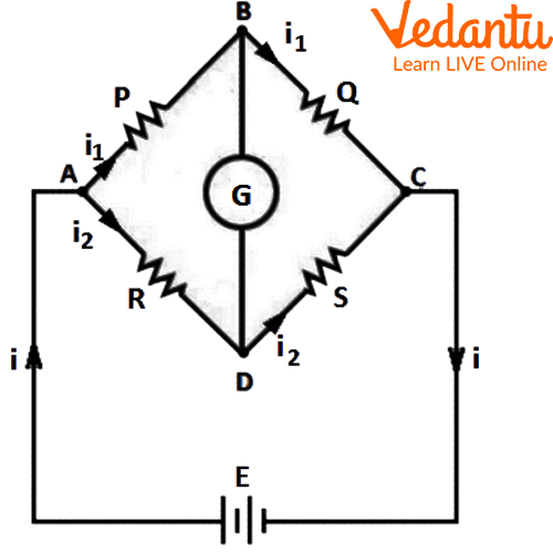
Metre bridge is one of the forms of Wheatstone bridge. Wheatstone bridge is used to measure resistance, capacitance and impedance and is based on the principle of null deflection. The arrangement of a Wheatstone bridge is shown in the diagram given below. It is an arrangement of four resistances, P, Q, R and S in quadrilateral form to determine one unknown resistance of any four of them. That means, no current will flow through the middle arm of the circuit, when the ratio of resistances in the two arms is equal. The balanced condition arises when we get $\dfrac{P}{Q}=\dfrac{R}{S}$.

Wheatstone Bridge
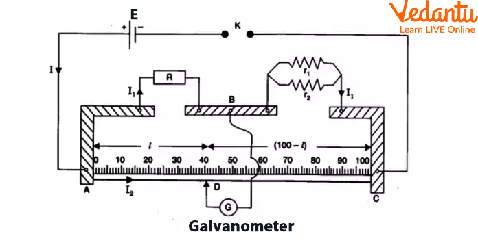
A metre bridge consists of thick strips of copper of negligible resistance. There are two gaps between these three strips. A jockey is connected to B through a galvanometer G. Across the two ends of wire, a battery and a key are connected.

Circuit Diagram Of Metre Bridge
One end of the galvanometer is made to slide on the metre bridge wire. With this jockey, we search for a point on the bridge which corresponds to a null point. A null point is a point where the galvanometer shows no deflection and the bridge is balanced. When the bridge is balanced, the ratio of wire AB to the resistance of wire BC will be equal to the ratio of resistance R to the unknown resistance which is connected between the gap BC. Least error is obtained when the null point lies at the midpoint of the wire.
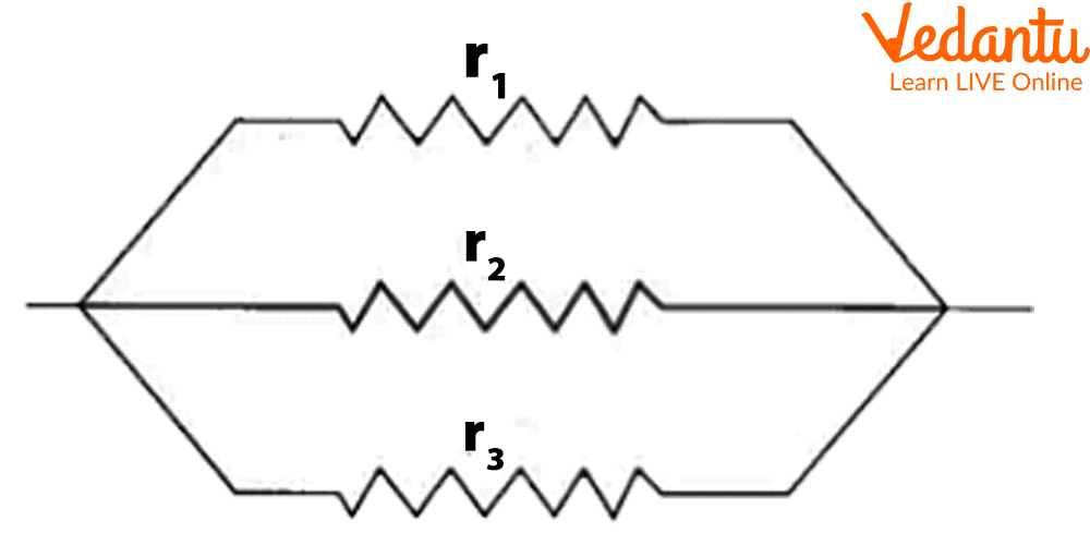
Parallel Combination of Resistances:
When resistances are connected in parallel.

Parallel Combination Of Resistances
We know that, when three resistors ${{r}_{1}}$ , ${{r}_{2}}$ and ${{r}_{3}}$ are connected in parallel, the resistance ${{R}_{P}}$ of their combination is given by,
${{R}_{P}}=\dfrac {{r_1}{r_2}{r_3}}{{r_1}{r_2}+{r_2}{r_3}+{r_3}{r_1}}$
Procedure
First of all, connect ${{r}_{1}}$ in the gap between B and C and tighten all plugs in the resistance box. Before making the connection, we should clean the ends of connections with sandpaper. Then connect the circuit as shown in the circuit diagram above.
Now, remove some plugs from the resistance box in order to get the suitable value of resistance R.
Get a null point D on the metre bridge by sliding the jockey between A and C ends. Then, we should note the length of AD and DC and value of resistance R.
We need to evaluate the experimental value of the equivalent resistance of parallel combination.
Now, perform this experiment two more times to obtain more values of resistance R. Then find out the mean value of unknown resistance.
Repeat the above steps by connecting ${{r}_{2}}$ and then by connecting resistances ${{r}_{1}}$ and ${{r}_{2}}$ in parallel as shown in the above circuit diagram and record the observations as shown in the table given below.
Observations
Verification of Parallel Combinations Theoretically and Experimentally.
Experimental value of $R_P$ = _____
Theoretical value of ${R_P}=\dfrac {{r_1}{r_2}}{{r_1}+{r_2}}$
Difference found (If any)=1.____
=2.____
Result
From this experiment, we can conclude that the theoretical and experimental value of ${{R}_{P}}$ is the same. Hence, we can say that we have verified a parallel combination of resistances using the metre bridge. So, the law of resistance in parallel is verified.
Precautions
We should note down the readings without any parallax.
The jockey should be moved gently over the metre bridge wire.
We should insert the key only while taking observations. So, we can avoid heating of resistance, otherwise its resistance will increase.
Lab Manual Questions
1. State the law of combination of resistance in parallel combination.
Ans: It states that when we connect two or more resistances in parallel combination, the reciprocal of equivalent resistance is equal to the sum of the reciprocal of all the individual resistances.
2. Which quantity remains the same in a parallel combination of resistors?
Ans: Voltage (V) remains the same in a parallel combination of resistors.
3. Why do we use a galvanometer in this experiment?
Ans: To find a balanced point or zero deflection point, we use the galvanometer in this experiment.
Viva Questions
1. When is Wheatstone bridge said to be balanced?
Ans: The Wheatstone bridge is said to be balanced when no current flows through the galvanometer.
2. Which material should we use for a metre bridge wire?
Ans: We should use Constantan or Manganin for the metre bridge wire because their temperature coefficient of resistance is almost negligible.
3. In what way, household appliances be connected?
Ans: Household appliances must be connected in parallel.
4. How many common points are required when we connect two resistors in parallel combination?
Ans: We require minimum two common points when we connect two resistors in parallel combination.
5. Name the type of connection that we should use in our house wiring.
Ans: We should use a parallel connection of appliances in our house wiring.
6. Why do we use copper blades in the metre bridge?
Ans: We use copper blades in the metre bridge because the resistance of copper is negligible.
7. What happens to the equivalent resistance when we connect three resistances in parallel combination?
Ans: The equivalent resistance decreases when we connect three resistances in parallel combination.
8. Can we use copper wire in the metre bridge?
Ans: We can not use copper wire in the metre bridge because its temperature coefficient value is high and its specific resistance value is low.
Practical Based Questions
Which instrument should we place at the centre of the Wheatstone bridge?
Inductor
Capacitor
Galvanometer
Ammeter
Ans: Option C - Galvanometer
Which of the following is true for the Wheatstone bridge?
We can use it to measure the internal resistance of the battery
We can use it to measure the electrical resistance
It is used to measure the intensity of magnetic field
It is used to measure the intensity of electric field
Ans: Option B - We can use it to measure the electrical resistance
In Wheatstone bridge, the instrument which we use as null detector is
Electroscope
Barometer
Spectrometer
Galvanometer
Ans: Option D - Galvanometer
Which of the following statements are correct?
The metre bridge is used to find unknown resistance and it is also called a slide wire bridge
The metre bridge is based on the principle of Wheatstone bridge
Option A and B
None of the above
Ans: Option C - Option A and B
Using a Wheatstone bridge, we can measure
Magnetic field
Radius of the bridge wire
Resistance
Electric field
Ans: Option C - Resistance
What happens if we connect two or more resistances in parallel combination?
The voltage through each resistance would be same
The current through each resistance would be same
Option A and B
None of the above
Ans: Option A - The voltage through each resistance would be same
The SI unit of resistance is
Kelvin
Voltage
Ohm
Tesla
Ans: Option C - Ohm
The SI unit of current is
Ampere
Ohm
Tesla
Newton
Ans: Option A - Ampere
Which instrument can be used to measure resistance?
Refractometer
Voltmeter
Ohmmeter
Barometer
Ans: Option C - Ohmmeter
The symbol for voltage is
T
Amp
Nm
V
Ans: Option D - V
Conclusion
From the above experiment, we can conclude that
The difference of theoretical and experimental value in parallel combinations is very small. So, the law of parallel combination of resistances is verified.
To decrease the net resistance of the circuit, different resistors can be connected in parallel.
The potential difference across all resistors remains the same and the net resistance produced is lowest when resistors are connected in parallel.
FAQs on Class 12 Physics The Law Of Combination Parallel Of Resistances Using A Metre Bridge Experiment
1. What is the principle behind verifying the law of combination (parallel) of resistances using a metre bridge in Class 12 Physics practicals?
The law is verified based on the Wheatstone bridge principle, which states that when the ratio of resistances in two arms of the bridge is equal, there is no current through the galvanometer indicating a balanced condition. This allows calculation of the equivalent parallel resistance using known and unknown resistors with the metre bridge apparatus.
2. List the main steps involved in the experiment to determine the equivalent resistance of two resistances connected in parallel using a metre bridge.
- Clean all connecting wire ends with sandpaper to ensure accurate contact.
- Insert one resistor in the metre bridge gap and complete the circuit as per diagram.
- Find the null point using a jockey by sliding it along the wire.
- Record the balanced length to calculate resistance using the Wheatstone bridge formula.
- Repeat the observation for the second resistor and then for their parallel combination.
Ensure all readings are taken only while the key is inserted to avoid unnecessary heating.
3. Why is it important to use Constantan or Manganin wire in the metre bridge for this experiment?
Constantan or Manganin are chosen for the metre bridge wire because both have a low temperature coefficient of resistance and offer high resistance, ensuring stability and accuracy in resistance measurements during the experiment.
4. How do you calculate the equivalent resistance when two resistors are connected in parallel in a metre bridge setup?
The equivalent parallel resistance (RP) is calculated using the formula:
1/RP = 1/R1 + 1/R2
Or, RP = (R1 × R2)/(R1 + R2). This value is then compared with the experimental value obtained from the metre bridge readings.
5. What precautions must be observed during the parallel combination of resistances using a metre bridge experiment to ensure accuracy in board exams?
- Ensure all connections are tight and wire ends are cleaned.
- Gently move the jockey to avoid damaging the bridge wire.
- Insert the battery key only while taking measurements to prevent heating.
- Note readings by avoiding parallax errors.
- Never touch the galvanometer terminals directly.
6. In board exams, which specific short questions related to the parallel combination of resistors using a metre bridge are frequently asked?
- State the law of combination of resistances in parallel.
- Which physical quantity remains constant in a parallel circuit?
- Why use a galvanometer in the Wheatstone bridge setup?
- Difference between experimental and theoretical resistance values.
- Advantages of parallel over series arrangements in circuits.
7. What are the common conceptual errors students make while answering questions on the law of parallel combination in Class 12 Physics?
- Mistaking which quantity remains constant (current vs. voltage) in parallel circuits.
- Forgetting to compare both theoretical and experimental resistance values.
- Mixing up the series and parallel resistance formulas.
- Ignoring the effect of contact resistance if wire ends are not properly cleaned.
8. Why is parallel connection preferred over series connection in household electrical wiring, as per the CBSE board marking trends?
In a parallel connection, each appliance receives the same voltage, and operation of one appliance doesn't affect others. The total resistance decreases, allowing higher current draw, and appliances can be switched on or off independently, which is an expected answer in 3- or 5-mark board questions.
9. How can you distinguish between series and parallel combinations of resistors in terms of exam-based application questions?
- In series combination, resistors have the same current but different voltage drops; in parallel combination, resistors have the same voltage across them but different currents.
- Series circuits are used where current control is needed; parallel circuits are used where maintaining voltage is more important.
10. What is the marking scheme for the experiment on the law of combination (parallel) of resistances using a metre bridge in the CBSE 2025–26 Physics Practical exam?
- Experiment procedure and accuracy: 8 marks
- Observation table and calculation: 3 marks
- Result and conclusion: 2 marks
- Viva and practical-based questions: 2 marks
Marks may slightly vary as per the school’s internal assessment guidelines, but the division broadly follows CBSE specifications.


