


How Does Magnetic Force Act on a Current Carrying Wire?
The force experienced by a current-carrying conductor placed in a magnetic field is a fundamental concept in electromagnetism. This effect forms the basis for the operation of devices like electric motors and is integral to the study of moving charges and magnetism.
Physical Basis of the Force
When a conductor carries electric current within a magnetic field, the moving charge carriers experience the Lorentz force. The collective effect produces a measurable force on the entire conductor, as explained by electromagnetic theory.
This interaction is important within the scope of Magnetic Effects of Current and Magnetism. The direction and magnitude of the force depend on the orientations of current and magnetic field.
Derivation of the Force Expression
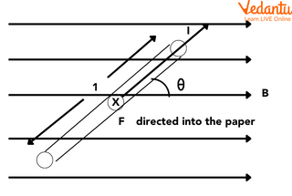
Consider a straight conductor of length $l$ and cross-sectional area $A$, carrying current $I$. Let $n$ be the number density of free electrons, and $e$ the elementary charge. In an external magnetic field $\vec{B}$, each electron with drift velocity $\vec{v}_d$ experiences a Lorentz force $\vec{f} = -e(\vec{v}_d \times \vec{B})$.
The total force on all $nAl$ electrons is given by:
$\vec{F} = (n A l) \vec{f} = -n A l e (\vec{v}_d \times \vec{B})$
Since $I = nAe v_d$, this reduces to the vector form:
$\vec{F} = I (\vec{l} \times \vec{B})$
The magnitude of the force is $F = I l B \sin \theta$, where $\theta$ is the angle between the conductor and the magnetic field.
Magnitude and Direction of the Force
The force on a current-carrying conductor in a uniform magnetic field depends on current, length, magnetic field strength, and the angle $\theta$. The force is maximum when the conductor is perpendicular to the field ($\theta = 90^\circ$), making $F_{max} = I l B$.
The force becomes zero when the conductor is parallel to the field ($\theta = 0^\circ$ or $180^\circ$), meaning $F = 0$.
| Orientation | Force Magnitude |
|---|---|
| Perpendicular ($\theta = 90^\circ$) | Maximum ($F = I l B$) |
| Parallel ($\theta = 0^\circ, 180^\circ$) | Zero ($F = 0$) |
Fleming's Left Hand Rule for Direction
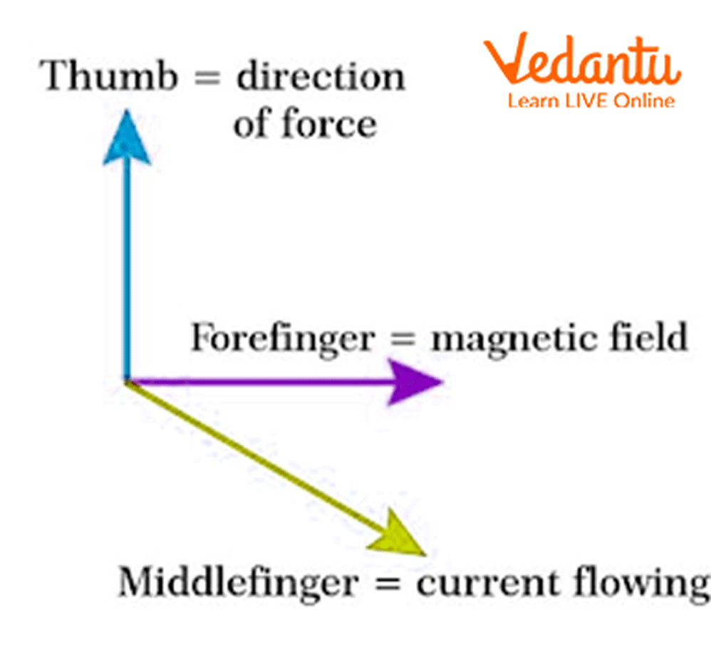
The direction of the force is given by Fleming’s left-hand rule. According to the rule: if the forefinger, middle finger, and thumb are held mutually perpendicular on the left hand, the forefinger points in the direction of the magnetic field, the middle finger in the direction of current, and the thumb shows the force direction.
This rule is essential for determining the force direction in electromagnetic devices such as motors and meters, where conductors carry current in magnetic fields.
Special Cases and Applications
The force expression $F = I l B \sin \theta$ applies to straight conductors in uniform magnetic fields. For a closed conducting loop in a uniform field, the net force is zero, but torque may arise, leading to rotational motion.
This physical principle underlies instruments described in Force on Current Carrying Conductor as well as in topics such as moving coil galvanometers and electric motors.
- Force is proportional to current magnitude
- Force depends on length within the field
- No force if current or field is zero
Illustrative Examples
Calculate the force on a conductor of length $0.6$ m, carrying $2$ A current, placed at right angles to a uniform magnetic field of $0.3$ T. Using $F = I l B$ with $\sin 90^\circ = 1$:
$F = 2 \times 0.6 \times 0.3 = 0.36$ N
If the same current and field exist, but the length is $0.3$ m and the conductor is at $30^\circ$ to the field, the force is:
$F = 2 \times 0.3 \times 0.3 \times \sin 30^\circ = 2 \times 0.09 \times 0.5 = 0.09$ N
Key Formulas and Related Concepts
The general vector expression for force on a current element in a magnetic field is $\vec{F} = I (\vec{l} \times \vec{B})$. For differential length $d\vec{l}$, $d\vec{F} = I (d\vec{l} \times \vec{B})$. The concept is related to the Magnetic Field Due to Infinite Wire and Magnetic Field Due to Straight Wire.
Summary Points
- Force is $F = I l B \sin \theta$ for straight conductors
- Direction is obtained by Fleming’s left-hand rule
- Maximum force when field and conductor are perpendicular
- Concepts apply in practical devices like motors
Understanding the force on a current-carrying conductor in a magnetic field is essential for electromagnetic device analysis and is covered in detail within Electric Field Lines and Properties and Electromagnetic Induction Revision Notes.
FAQs on Understanding the Force on a Current Carrying Conductor in a Magnetic Field
1. What is the force on a current-carrying conductor placed in a magnetic field?
The force on a current-carrying conductor in a magnetic field is the mechanical push or pull experienced due to the interaction of electric current and magnetic field lines. This force is given by Fleming's left-hand rule and can be calculated using the following formula:
- F = BIL sin θ, where:
- F = force (in newtons)
- B = magnetic field strength (in teslas)
- I = current in the conductor (in amperes)
- L = length of the conductor in the magnetic field (in metres)
- θ = angle between current direction and magnetic field
2. State Fleming's left-hand rule.
Fleming's left-hand rule helps predict the direction of force experienced by a current-carrying conductor in a magnetic field. According to this rule:
- Stretch your left hand so that the thumb, forefinger, and middle finger are mutually perpendicular.
- Forefinger points in the direction of the magnetic field (N to S).
- Middle finger shows the direction of the current.
- Thumb gives the direction of the force (motion).
3. What factors affect the magnitude of force on a current-carrying conductor in a magnetic field?
The magnitude of force on a current-carrying conductor depends on:
- Magnetic field strength (B): Stronger magnetic fields produce more force.
- Current (I): Higher current increases the force.
- Length of conductor (L) inside the field: Longer conductor, greater force.
- Angle (θ) between the conductor and magnetic field: Force is maximum when the angle is 90° (sin 90° = 1).
4. Why is the force maximum when the conductor is perpendicular to the magnetic field?
The force on a current-carrying conductor is maximum when it is at a 90° angle to the magnetic field because the sine function (sin θ) reaches its highest value at 90°.
- When θ = 90°, sin 90° = 1, so F = BIL, the maximum possible value.
- If the conductor is parallel (θ = 0°), sin 0° = 0, so the force becomes zero.
5. Name some devices that work on the principle of force on a current-carrying conductor in a magnetic field.
Several devices operate on the principle of force experienced by a current-carrying conductor in a magnetic field, including:
- Electric motors
- Loudspeakers
- Galvanometers
- Electric meters (ammeters and voltmeters)
6. What is the direction of force on a current-carrying conductor in a magnetic field?
The direction of the force on a current-carrying conductor in a magnetic field is determined by Fleming's left-hand rule.
- The forefinger points in the direction of the magnetic field (N to S).
- The middle finger points in the direction of the current.
- The thumb gives the direction of force or motion on the conductor.
7. Derive the expression for the force on a current-carrying conductor placed in a uniform magnetic field.
To derive the expression for the force:
- If a conductor of length L carrying current I is placed in a uniform magnetic field B such that the conductor makes an angle θ with the field,
- The force F experienced by the conductor is: F = BIL sin θ
- Here:
- B is magnetic field strength (tesla)
- I is current (ampere)
- L is length of conductor (metre)
- θ is the angle between current and magnetic field
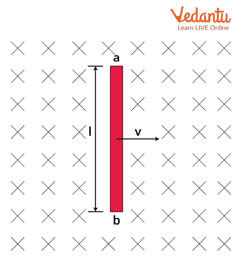
8. How do you demonstrate the force on a current-carrying conductor in a magnetic field in the laboratory?
To demonstrate the force on a current-carrying conductor:
- Set up a horseshoe magnet and place a straight wire between its poles.
- Connect the wire to a power source to allow current to flow through it.
- The wire is observed to move, showing that it experiences a force.
9. What will happen if the direction of current in the conductor is reversed?
If the direction of current is reversed in a conductor placed in a magnetic field, the direction of the force acting on the conductor also reverses.
- This is because the force direction depends on the direction of both current and magnetic field.
- Fleming's left-hand rule can be used to predict the new direction.
10. Why is the study of the force on a current-carrying conductor important for physics students?
The study of force on a current-carrying conductor is vital because:
- It explains the working of everyday devices like fans, motors, and meters.
- It is a key topic in the syllabus for understanding the magnetic effect of electric current.
- You gain insight into practical physics and can answer both theoretical and numerical problems in exams.