


How Do LR and RC Circuits Work? Principles, Formulas, and Real-life Uses
LR and RC circuits are fundamental electrical circuits that include resistors with either inductors or capacitors, respectively. These circuits demonstrate important concepts such as transient behaviour, time constant, and energy storage mechanisms which are essential in both theoretical and practical electronics, especially within the context of JEE Main Physics.
Basic Components in LR and RC Circuits
The behaviour of LR and RC circuits is determined by the properties of resistors, inductors, and capacitors. A resistor opposes the flow of electric current, an inductor stores energy in its magnetic field, and a capacitor stores energy in an electric field. Each component imparts distinctive characteristics to these circuits.
The correct functioning and response of LR and RC circuits can be better understood by analysing the combination and configuration of these components, as detailed in fundamental circuit laws.
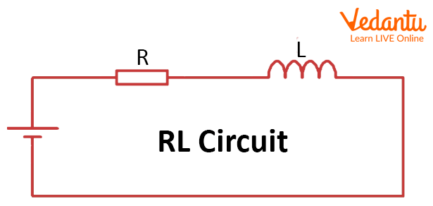
LR Circuit: Structure and Analysis
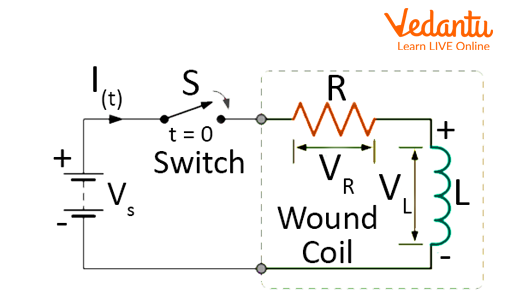
An LR circuit consists of a resistor (R) and an inductor (L) either in series or parallel with an external voltage or current source. The key behaviour in LR circuits is governed by the gradual buildup of current, which is opposed by the inductor.
Upon switching on a battery in a series LR circuit, the current does not increase instantly but rises exponentially according to the following law:
$ I(t) = \dfrac{V}{R}\left[1 - e^{-\dfrac{R t}{L}}\right] $
Here, $I(t)$ is the current at time $t$, $V$ is the applied voltage, $R$ is the resistance, and $L$ is the inductance. The time constant for an LR circuit is $\tau = \dfrac{L}{R}$, representing the time taken for the current to reach approximately $63\%$ of its final value.
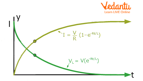
In steady-state (long after switching), the current reaches a maximum of $I_0 = \dfrac{V}{R}$. During switch-off, the current decays according to $I(t) = I_0 e^{-\dfrac{R t}{L}}$.
To further explore the theory of LR circuits, refer to LR and RC Circuits Overview.
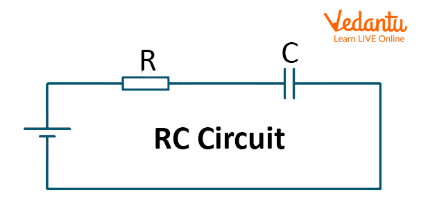
RC Circuit: Structure and Analysis
An RC circuit consists of a resistor (R) and a capacitor (C), either in series or parallel with a voltage or current source. The charging and discharging of the capacitor define the time-dependent behaviour of this circuit.
When a DC voltage is suddenly applied, the capacitor charges gradually. The voltage across the capacitor over time is given by:
$ V_C(t) = V [1 - e^{-\dfrac{t}{RC}} ] $
Here, $V$ is the source voltage, $t$ is time, $R$ is resistance, and $C$ is capacitance. The time constant $\tau = RC$ determines the rate of charging or discharging - after time $\tau$, the capacitor charges to about $63\%$ of its maximum voltage.
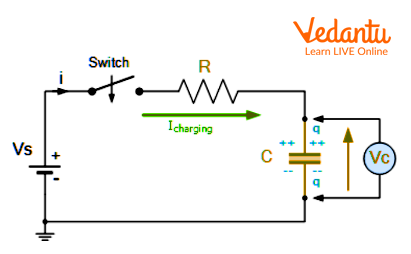
The charging current in the circuit varies with time as $I(t) = \dfrac{V}{R}e^{-\dfrac{t}{RC}}$. In steady-state, the current becomes zero and the capacitor voltage equals the source voltage.
In RC discharge, the stored charge leaves the capacitor through the resistor and follows a similar exponential law but in reverse. More detailed information is available in Understanding RC Circuits.
Key Equations and Time Constants in LR and RC Circuits
The exponential behaviour of LR and RC circuits is governed by their respective time constants. These time constants control how quickly transient processes such as charging, discharging, or current growth complete within the circuit.
| Parameter | Expression |
|---|---|
| LR circuit time constant | $\tau = \dfrac{L}{R}$ |
| RC circuit time constant | $\tau = RC$ |
| Current in LR (charging) | $I(t) = \dfrac{V}{R}\left[1 - e^{-\dfrac{Rt}{L}}\right]$ |
| Current in RC (discharging) | $I(t) = I_0 e^{-\dfrac{t}{RC}}$ |
| Voltage across capacitor | $V_C(t) = V[1 - e^{-\dfrac{t}{RC}}]$ |
Comparison of LR and RC Circuits
LR and RC circuits both display exponential responses to changes in applied sources, but the mechanism of energy storage differs. LR circuits store energy in the magnetic field of the inductor, whereas RC circuits store energy in the electric field of the capacitor.
| Aspect | LR Circuit |
|---|---|
| Energy Storage | Magnetic Field (Inductor) |
| Initial Response to Switching On | Zero current, increases over time |
| Steady-State Response | Current saturates at $\dfrac{V}{R}$ |
| Time Constant | $\dfrac{L}{R}$ |
| Main Application | Chokes, Filters |
| Aspect | RC Circuit |
|---|---|
| Energy Storage | Electric Field (Capacitor) |
| Initial Response to Switching On | Maximum current, decreases over time |
| Steady-State Response | Current is zero, capacitor charged |
| Time Constant | $RC$ |
| Main Application | Filters, Timing Circuits |
Practical Applications of LR and RC Circuits
LR circuits are used in applications such as chokes in fluorescent lamps, signal filtering, and inductive sensors. RC circuits function as timing circuits, filters (such as low-pass and high-pass filters), and in signal processing modules.
- RC circuits for timing in electronic devices
- LR circuits in signal filters and chokes
- Use in basic analog electronic systems
- Voltage division and wave shaping
Studying these concepts is essential for advanced topics in current electricity. Detailed discussions on electrical concepts are available at Current Electricity Concepts.
Sample Calculation: Time Constant in LR and RC Circuits
For an LR circuit with $L = 2 \ \text{H}$ and $R = 100\ \Omega$, the time constant is $\tau = \dfrac{2}{100} = 0.02\ \text{s}$. For an RC circuit with $R = 1 \ \text{k}\Omega$ and $C = 10\ \mu\text{F}$, $\tau = 1000 \times 10 \times 10^{-6} = 0.01\ \text{s}$.
Summary Table: LR vs RC Circuits
| Circuit Parameter | LR Circuit | RC Circuit |
|---|---|---|
| Time Constant | $\tau = \dfrac{L}{R}$ | $\tau = RC$ |
| Initial Current | $0$ | $\dfrac{V}{R}$ |
| Steady-State Current | $\dfrac{V}{R}$ | $0$ |
| Energy Storage | Inductor (magnetic field) | Capacitor (electric field) |
| Primary Use | Chokes, Filters | Filters, Timers |
A solid understanding of LR and RC circuits is central to mastering electrical circuit analysis and is frequently assessed in JEE examinations. For foundational laws relevant to these circuits, study Laws of Motion Fundamentals and Ohm's Law and Resistance.
FAQs on Understanding LR and RC Circuits: Fundamentals and Applications
1. What is an LR circuit?
An LR circuit is an electrical circuit consisting of an inductor (L) and a resistor (R) connected in series or parallel. Key points:
- The inductor opposes changes in current due to its inductance.
- The resistor limits the current and causes energy dissipation as heat.
- When supply voltage is applied, the current increases gradually, not instantly, due to the inductor's opposition.
- Such circuits demonstrate important concepts like time constant, growth and decay of current, and transient response.
2. What is an RC circuit?
An RC circuit consists of a resistor (R) and a capacitor (C) connected in series or parallel. Main characteristics include:
- The resistor limits the flow of current.
- The capacitor stores and releases electrical energy.
- RC circuits exhibit charging and discharging behavior of the capacitor.
- These circuits are fundamental in timing applications and signal filtering.
3. What is a time constant in LR and RC circuits?
The time constant measures how quickly current or voltage changes in LR or RC circuits. Key points:
- For an LR circuit, time constant τ = L/R.
- For an RC circuit, time constant τ = RC.
- It defines the time to reach about 63% of the final value after a voltage is applied or removed.
- It determines the speed of transient response in both circuits.
4. Describe the growth of current in an LR circuit after switching on the supply.
Current in an LR circuit increases gradually when a voltage supply is switched on. Process details:
- Initially, the inductor opposes sudden current change (Lenz's Law).
- Current rises exponentially over time and approaches a maximum steady value of V/R.
- The growth follows the equation: I = (V/R)(1 - e-tR/L), where V is supply voltage.
- The time taken to reach steady state depends on the time constant (L/R).
5. Explain the charging process of a capacitor in an RC circuit.
When a capacitor is charged through a resistor in an RC circuit, the process is gradual, not instantaneous. Key stages:
- Initially, the current is maximum and the capacitor voltage is zero.
- As the capacitor charges, current decreases exponentially while voltage across the capacitor increases.
- The voltage across the capacitor at time t: VC = V(1 - e-t/RC), where V is supply voltage.
- The process is characterized by the time constant (RC).
6. What is the difference between LR and RC circuits?
LR and RC circuits have different reactive components responsible for their behavior.
- LR circuit: Contains a resistor (R) and an inductor (L); inductance opposes current change.
- RC circuit: Contains a resistor (R) and capacitor (C); capacitance stores and releases charge.
- In LR, the inductor delays current buildup and decay; in RC, the capacitor affects voltage change across itself.
- Applications differ: LR for filters and inductive loads, RC for timing and filtering.
7. What happens to current in an RL circuit when the switch is opened?
When the switch in an RL circuit is opened, the current does not stop instantly due to the inductor's stored energy. Essential points:
- The inductor produces a back EMF that maintains current flow momentarily.
- Current decreases exponentially to zero, following the equation: I = I0e-tR/L.
- This behavior helps prevent sudden current drops and protects circuit components from voltage spikes.
8. State some practical applications of LR and RC circuits.
LR and RC circuits have diverse real-world applications in electronics and electrical engineering. Examples include:
- LR circuits: Used in filters, chokes, tuning radios, and managing inductive loads.
- RC circuits: Utilized in timers, oscillators, audio equipment, and signal processing circuits.
- Both types are essential in switch debounce, smoothing, and pulse shaping circuits.
9. How do you calculate the time constant of an RC circuit?
The time constant (τ) for an RC circuit quantifies how quickly a capacitor charges or discharges. To calculate:
- Use the formula: τ = RC
- Where R = resistance in ohms (Ω) and C = capacitance in farads (F)
- The time constant τ is the time taken for the voltage (or charge) to change by approximately 63% of the total difference from initial to final value.
10. What is the equation for current in an RL circuit during the decay phase?
During current decay in an RL circuit (when supply is removed), the current decreases exponentially. The equation is:
- I = I0e-tR/L
- I0 = initial current at time t = 0
- t = time elapsed since removing supply
- R = resistance, L = inductance
- This formula illustrates the transient response and use of the time constant (L/R).
11. What factors affect the rate of charge and discharge in RC circuits?
The rate of charge and discharge in RC circuits depends on component values. Major factors include:
- Resistance (R): Higher resistance increases the time constant, slowing charge/discharge.
- Capacitance (C): Larger capacitance also increases the time constant, causing slower capacitive charging and discharging.
- Their product (RC) directly sets the rate at which voltage and current change.