


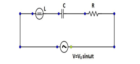
For the LCR circuit, shown here, the current is observed to lead the applied voltage. An additional capacitor $C'$, when joined with the capacitor $C$ present in the circuit, makes the power factor of the circuit unity. The capacitor $C'$ must have been connected in:
(A) $\dfrac{{1 - {\omega ^2}LC}}{{{\omega ^2}L}}$parallel with $C$
(B) $\dfrac{{1 - {\omega ^2}LC}}{{{\omega ^2}L}}$series with $C$
(C) $\dfrac{C}{{\left( {{\omega ^2}LC - 1} \right)}}$parallel with $C$
(D) $\dfrac{C}{{\left( {{\omega ^2}LC - 1} \right)}}$series with $C$
Answer
233.1k+ views
Hint: Given that the power factor of the circuit is unity. The difference of impedance reactance and capacitive reactance is zero. So we need to compute their values and solve the equation to find the answer.
Formula Used: The formulae used in the solution are given here.
The impedance of circuit is given by $Z = \sqrt {{R^2} + {{\left( {\omega L - \dfrac{1}{{\omega C}}} \right)}^2}} $ where $R$ is the resistance and $C$ is the capacitance and $\omega = 2\pi f$ where $f$ is the frequency.
${X_L}$ is impedance reactance and ${X_C}$ is capacitive reactance.
Complete Step by Step Solution: In general power is the capacity to do work. In the electrical domain, electrical power is the amount of electrical energy that can be transferred to some other form (heat, light etc.) per unit time. Mathematically it is the product of voltage drop across the element and current flowing through it. Considering first the DC circuits, having only DC voltage sources, the inductors and capacitors behave as short circuits and open circuits respectively in steady state.
Now coming to AC circuit, here both inductor and capacitor offer a certain amount of impedance given by:
${X_L} = 2\pi fL$ and ${X_C} = \dfrac{1}{{2\pi fC}}$.
The inductor of impedance $L$ stores electrical energy in the form of magnetic energy and capacitor of capacitance $C$ stores electrical energy in the form of electrostatic energy.
Neither of them dissipates it. Further, there is a phase shift between voltage and current.
The cosine of this phase difference is called electrical power factor. This factor ($ - 1 < \cos \varphi < 1$ ) represents the fraction of the total power that is used to do the useful work. The other fraction of electrical power is stored in the form of magnetic energy or electrostatic energy in the inductor and capacitor respectively.
Given that, the current is observed to lead the applied voltage in the LCR circuit. An additional capacitor $C'$, when joined with the capacitor $C$ present in the circuit, makes the power factor of the circuit unity.
Thus, $\cos \varphi = 1$.
$\cos \varphi = \dfrac{R}{{\sqrt {{R^2}\left[ {\omega L - \dfrac{1}{{\omega \left( {C + C'} \right)}}} \right]} }} = 1$.
On solving the equation above, we get,
$ \Rightarrow \omega L = \dfrac{1}{{\omega \left( {C + C'} \right)}}$
The capacitor $C'$ must have magnitude:
$C' = \dfrac{{1 - {\omega ^2}LC}}{{{\omega ^2}L}}$
Adding capacitor of capacitance C' in parallel of C, the reactance will be:
${X_L} - {X_C} = \omega L - \dfrac{1}{{\omega \left( {C + C'} \right)}}$
Since, ${X_L} - {X_C} = 0$,
$\omega L - \dfrac{1}{{\omega \left( {C + C'} \right)}} = 0$
$ \Rightarrow C' = \dfrac{1}{{{\omega ^2}L}} - C$
Connecting the capacitors in parallel, $C' = \dfrac{{1 - {\omega ^2}LC}}{{{\omega ^2}L}}$
Hence the correct answer is Option A.
Note: The impedance of circuit is given by $Z = \sqrt {{R^2} + {{\left( {\omega L - \dfrac{1}{{\omega C}}} \right)}^2}} $ and the current lag voltage by $\tan \varphi = \dfrac{{{X_L} - {X_C}}}{R} = \dfrac{{\omega L - \dfrac{1}{{\omega C}}}}{R}$
For the power factor to be one the current and voltage have to be in the same phase i.e. $\varphi $ has to be zero.
Adding capacitor of capacitance $C'$ in series of $C$, the reactance will be
${X_L} - {X_C} = \omega L - \dfrac{1}{{\omega \left( {C + C'} \right)}}$
$ \Rightarrow \omega L - \dfrac{1}{{\omega \left( {\dfrac{{CC'}}{{C + C'}}} \right)}}$
Which gives us,
$ \Rightarrow {\omega ^2}LCC' = C + C'$
The value of $C'$ when connected in series will be,
Thus, $C' = \dfrac{C}{{{\omega ^2}LC - 1}}$.
Recently Updated Pages
JEE Main 2026 Session 2 Registration Open, Exam Dates, Syllabus & Eligibility
JEE Main 2023 April 6 Shift 1 Question Paper with Answer Key
JEE Main 2023 April 6 Shift 2 Question Paper with Answer Key
JEE Main 2023 (January 31 Evening Shift) Question Paper with Solutions [PDF]
JEE Main 2023 January 30 Shift 2 Question Paper with Answer Key
JEE Main 2023 January 25 Shift 1 Question Paper with Answer Key
Trending doubts
JEE Main Marking Scheme 2026- Paper-Wise Marks Distribution and Negative Marking Details
Why does capacitor block DC and allow AC class 12 physics JEE_Main
Understanding Average and RMS Value in Electrical Circuits
Understanding Collisions: Types and Examples for Students
Ideal and Non-Ideal Solutions Explained for Class 12 Chemistry
Understanding Atomic Structure for Beginners
Other Pages
JEE Advanced Weightage 2025 Chapter-Wise for Physics, Maths and Chemistry
CBSE Class 12 Physics Set 2 (55/2/2) 2025 Question Paper & Solutions
Inductive Effect and Its Role in Acidic Strength
Degree of Dissociation: Meaning, Formula, Calculation & Uses
Units and Measurements Mock Test for JEE Main 2025-26 Preparation
Chemistry Question Papers for JEE Main, NEET & Boards (PDFs)