


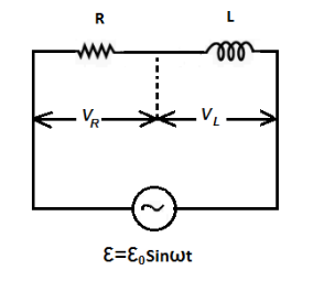
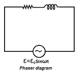
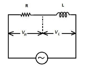
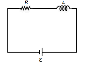
(a) An ac circuit as shown in the figure has an inductor of inductance \[L\] and a resistor of resistance connected in series. Using the phasor diagram, explain why the voltage in the circuit will lead the current in phase.
(b)The potential difference across the resistor is \[160\,{\text{V}}\] and that across the inductor is \[120\,{\text{V}}\]. Find the effective value of the applied voltage. If the effective current in the circuit be \[1.0\,{\text{A}}\]. Calculate the total impedance of the circuit.
(c) What will be the potential difference in the circuit when direct current is passed through the circuit?
Answer
581.7k+ views
Hint: First of all, we will draw the diagrams for which the solution will be easy to proceed. After that for the impedance part, we will individually find out resistance and the impedance. To calculate the effective value of the added voltage, we will use both the voltages of resistor and the inductor.
Complete step by step answer:
In the given question, we are supplied with the following data:
The figure has an inductor of inductance \[L\] and a resistor of resistance connected in series.
$(a)$ We are asked to find out why the voltage in the circuit will lead the current in phase.
\[\varepsilon \] is \[\phi \] ahead of \[i\] . For better understanding we draw the following diagrams:
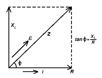
This is due to the fact that \[i\] and \[R\] are in phase and i.e., \[Z\] and \[\varepsilon \] are in phase as \[\varepsilon = {\varepsilon _0}\sin \omega t\] from diagram
\[i = \dfrac{{{\varepsilon _0}}}{Z}\sin \left( {\omega t - \phi } \right)\]
Where, \[\phi = {\tan ^{ - 1}}\dfrac{{{X_L}}}{R}\]
$(b)$ We are given that the current is \[1\,{\text{A}}\] .
\[i = 1.0A\] (Given)
Potential difference across the inductor is given as \[{V_L} = 120V\].
We know from the Ohm’s law,
\[{V_L} = i{X_L}\] …… (1)
Where,
\[{V_L}\] indicates the voltage across the inductor.
\[i\] indicates the current flowing through it.
\[{X_L}\] indicates the inductive reactance.
Now by substituting the required values in the equation (1), we get:
\[
{V_L} = i{X_L} \\
\Rightarrow{X_L} = \dfrac{{120}}{1} \\
\Rightarrow{X_L} = 120\,{\Omega } \\
\]
Potential difference across the resistor is \[{V_R} = 160\,{\text{V}}\] .
We know,
\[{V_R} = iR\] …… (2)
Where,
\[{V_R}\] indicates the voltage across the resistor.
\[i\] indicates the current flowing through it.
\[R\] indicates the resistance of the resistor.
$
{V_R} = iR \\
\Rightarrow 160 = 1 \times R \\
\Rightarrow R = \dfrac{{160}}{1} \\
\Rightarrow R = 160\,{\Omega } \\
\Rightarrow{V_{net}} = \sqrt {{V_R}^2 + {V_L}^2} \\
\Rightarrow{V_{net}} = \sqrt {{{\left( {160} \right)}^2} + {{\left( {120} \right)}^2}} \\
\Rightarrow{V_{net}} = \sqrt {25600 + 14400} \\
\therefore{V_{net}} = 200\,{\text{V}} \\$
Hence, the effective value of applied voltage is \[200\,{\text{V}}\] .
Now, we will find the net impedance, which is given by the following manipulation:
$
Z = \sqrt {{R^2} + {X_L}^2} \\
\Rightarrow Z = \sqrt {{{\left( {160} \right)}^2} + {{\left( {120} \right)}^2}} \\
\therefore Z = 200\,{\Omega} \\$
Hence, the total impedance of the circuit is \[200\,{\Omega }\] .
$(c)$ When direct current is passed through the circuit then \[R\] will be zero at \[t = \omega\], inductor will act as plane wire and potential drop will only act occur at \[R\,\]
\[\left( {i = \dfrac{\varepsilon }{R}} \right)\]
For intermediate time, we can write:
\[E = iR + \dfrac{{Ldi}}{{dt}}\]
In this case, current \[i\] will vary accordingly.
Note: This problem can be solved if you have a sound knowledge about phasor diagrams and alternating current. It should be remembered that in a purely capacitive circuit, the current will lead the voltage. Impedance is the net effective resistance offered by an electric circuit which contains resistor and inductor.
Complete step by step answer:
In the given question, we are supplied with the following data:
The figure has an inductor of inductance \[L\] and a resistor of resistance connected in series.
$(a)$ We are asked to find out why the voltage in the circuit will lead the current in phase.
\[\varepsilon \] is \[\phi \] ahead of \[i\] . For better understanding we draw the following diagrams:
This is due to the fact that \[i\] and \[R\] are in phase and i.e., \[Z\] and \[\varepsilon \] are in phase as \[\varepsilon = {\varepsilon _0}\sin \omega t\] from diagram
\[i = \dfrac{{{\varepsilon _0}}}{Z}\sin \left( {\omega t - \phi } \right)\]
Where, \[\phi = {\tan ^{ - 1}}\dfrac{{{X_L}}}{R}\]
$(b)$ We are given that the current is \[1\,{\text{A}}\] .
\[i = 1.0A\] (Given)
Potential difference across the inductor is given as \[{V_L} = 120V\].
We know from the Ohm’s law,
\[{V_L} = i{X_L}\] …… (1)
Where,
\[{V_L}\] indicates the voltage across the inductor.
\[i\] indicates the current flowing through it.
\[{X_L}\] indicates the inductive reactance.
Now by substituting the required values in the equation (1), we get:
\[
{V_L} = i{X_L} \\
\Rightarrow{X_L} = \dfrac{{120}}{1} \\
\Rightarrow{X_L} = 120\,{\Omega } \\
\]
Potential difference across the resistor is \[{V_R} = 160\,{\text{V}}\] .
We know,
\[{V_R} = iR\] …… (2)
Where,
\[{V_R}\] indicates the voltage across the resistor.
\[i\] indicates the current flowing through it.
\[R\] indicates the resistance of the resistor.
$
{V_R} = iR \\
\Rightarrow 160 = 1 \times R \\
\Rightarrow R = \dfrac{{160}}{1} \\
\Rightarrow R = 160\,{\Omega } \\
\Rightarrow{V_{net}} = \sqrt {{V_R}^2 + {V_L}^2} \\
\Rightarrow{V_{net}} = \sqrt {{{\left( {160} \right)}^2} + {{\left( {120} \right)}^2}} \\
\Rightarrow{V_{net}} = \sqrt {25600 + 14400} \\
\therefore{V_{net}} = 200\,{\text{V}} \\$
Hence, the effective value of applied voltage is \[200\,{\text{V}}\] .
Now, we will find the net impedance, which is given by the following manipulation:
$
Z = \sqrt {{R^2} + {X_L}^2} \\
\Rightarrow Z = \sqrt {{{\left( {160} \right)}^2} + {{\left( {120} \right)}^2}} \\
\therefore Z = 200\,{\Omega} \\$
Hence, the total impedance of the circuit is \[200\,{\Omega }\] .
$(c)$ When direct current is passed through the circuit then \[R\] will be zero at \[t = \omega\], inductor will act as plane wire and potential drop will only act occur at \[R\,\]
\[\left( {i = \dfrac{\varepsilon }{R}} \right)\]
For intermediate time, we can write:
\[E = iR + \dfrac{{Ldi}}{{dt}}\]
In this case, current \[i\] will vary accordingly.
Note: This problem can be solved if you have a sound knowledge about phasor diagrams and alternating current. It should be remembered that in a purely capacitive circuit, the current will lead the voltage. Impedance is the net effective resistance offered by an electric circuit which contains resistor and inductor.
Recently Updated Pages
Master Class 12 Economics: Engaging Questions & Answers for Success
Master Class 12 Physics: Engaging Questions & Answers for Success
Master Class 12 English: Engaging Questions & Answers for Success
Master Class 12 Social Science: Engaging Questions & Answers for Success
Master Class 12 Maths: Engaging Questions & Answers for Success
Master Class 12 Business Studies: Engaging Questions & Answers for Success
Trending doubts
Which are the Top 10 Largest Countries of the World?
What are the major means of transport Explain each class 12 social science CBSE
Draw a labelled sketch of the human eye class 12 physics CBSE
What is a transformer Explain the principle construction class 12 physics CBSE
Why cannot DNA pass through cell membranes class 12 biology CBSE
Differentiate between insitu conservation and exsitu class 12 biology CBSE