
A capacitor is to be provided smoothing for a half wave rectifier. In which of the following diagrams is the capacitor correctly connected?
A.
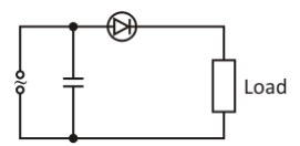
B.
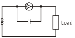
C.
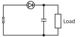
D.
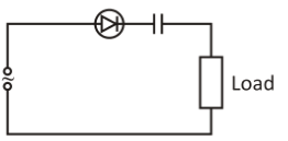


Answer
566.4k+ views
Hint: First of all, we will look for the capacitor to be connected in parallel with the load. A rectifier only allows one half cycle of the alternating current waveform to pass through it, in which it blocks the other half of that waveform.
Complete answer:
In the given question, we are given four circuit diagrams.Each diagram has a different way of connection of the circuit elements such as load and capacitor.We are asked to find out which one of the following circuits, has a correct connection of capacitor, so that it provides smoothing for a half wave rectifier.
As we are asked for smoothing, there should be the capacitor connected with the load in parallel without the involvement of the diode. However, except for the figure C, the capacitor is not connected to the load in parallel.The correct relation of the capacitor to the half-wave rectified mesh shape is only given by figure C. The half-wave rectifier is linked without the capacitor, as seen. Next to it, is the output waveform attached.
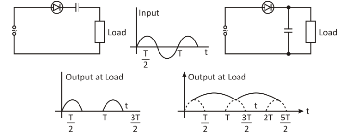
The capacitor is charged to the peak value of the applied AC during the positive period. Voltage, and then when the applied voltage starts to fall, it is discharged by R. Because of the broad time-constant RC, the discharge takes place slowly, and then C is charged to the peak value of the voltage again. The phase of charge-discharge takes place continuously and so as seen diagrammatically above the voltage across the C-R combination is a ‘ripple’ voltage. The average DC with the C-R structure, the voltage is almost equal to the value of the peak voltage, which is better and hence reduces the difference in voltage (filters).
The correct option is C.
Note:While answering the question, most of the students tend to make mistake in order to search for the capacitor to be connected with the load in parallel, they choose figure A. But if we look in the figure A, there is involvement of a diode in between the capacitor and the load. Hence, it is not correct. Please take care of that.
Complete answer:
In the given question, we are given four circuit diagrams.Each diagram has a different way of connection of the circuit elements such as load and capacitor.We are asked to find out which one of the following circuits, has a correct connection of capacitor, so that it provides smoothing for a half wave rectifier.
As we are asked for smoothing, there should be the capacitor connected with the load in parallel without the involvement of the diode. However, except for the figure C, the capacitor is not connected to the load in parallel.The correct relation of the capacitor to the half-wave rectified mesh shape is only given by figure C. The half-wave rectifier is linked without the capacitor, as seen. Next to it, is the output waveform attached.

The capacitor is charged to the peak value of the applied AC during the positive period. Voltage, and then when the applied voltage starts to fall, it is discharged by R. Because of the broad time-constant RC, the discharge takes place slowly, and then C is charged to the peak value of the voltage again. The phase of charge-discharge takes place continuously and so as seen diagrammatically above the voltage across the C-R combination is a ‘ripple’ voltage. The average DC with the C-R structure, the voltage is almost equal to the value of the peak voltage, which is better and hence reduces the difference in voltage (filters).
The correct option is C.
Note:While answering the question, most of the students tend to make mistake in order to search for the capacitor to be connected with the load in parallel, they choose figure A. But if we look in the figure A, there is involvement of a diode in between the capacitor and the load. Hence, it is not correct. Please take care of that.
Recently Updated Pages
Master Class 12 Economics: Engaging Questions & Answers for Success

Master Class 12 Physics: Engaging Questions & Answers for Success

Master Class 12 English: Engaging Questions & Answers for Success

Master Class 12 Social Science: Engaging Questions & Answers for Success

Master Class 12 Maths: Engaging Questions & Answers for Success

Master Class 12 Business Studies: Engaging Questions & Answers for Success

Trending doubts
Which are the Top 10 Largest Countries of the World?

What are the major means of transport Explain each class 12 social science CBSE

Draw a labelled sketch of the human eye class 12 physics CBSE

Why cannot DNA pass through cell membranes class 12 biology CBSE

Differentiate between insitu conservation and exsitu class 12 biology CBSE

Draw a neat and well labeled diagram of TS of ovary class 12 biology CBSE


