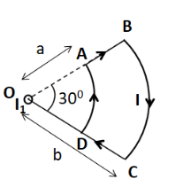
A current loop ABCD is held fixed on the plane of the paper as shown in the figure. The arc BC $ \left( {{\text{radius}} = b} \right) $ and DA $ \left( {{\text{radius}} = a} \right) $ of the loop are joined by two straight wires AB and CD. A steady current $ I $ is flowing in the loop. Angle made by AB and CD at the origin O is $ {30^ \circ } $ . Another straight thin wire with steady current $ {I_1} $ flowing out of the plane of the paper is kept at the origin. Due to the presence of the current $ {I_1} $ at the origin:

(A) The forces on AB and DC are zero
(B) The forces on AD and BC are zero
(C) The magnitude of the net force on the loop is given by $ \dfrac{{{I_1}I}}{{4\pi }}{\mu _0}\left[ {2\left( {b - a} \right) + \dfrac{\pi }{3}\left( {a + b} \right)} \right] $
(D) The magnitude of the net force on the loop is given by $ \dfrac{{{\mu _0}I{I_1}}}{{24ab}}\left( {b - a} \right) $

Answer
563.1k+ views
Hint : To solve this question, we need to draw magnetic field lines due to the current $ {I_1} $ . Then we have to use the expression of the force on a current carrying wire to get the forces on the individual wire segments.
Formula Used: The formula used in solving this question is given by
$ \vec F = I\left( {\vec l \times \vec B} \right) $
Here $ \vec F $ is the force acting on a wire carrying a current $ I $ which is of length $ l $ and is placed in a uniform magnetic field $ \vec B $ . Here the direction of $ \vec l $ vector is taken in the direction of the current $ I $ .
Complete step by step answer
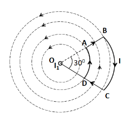
As the straight thin wire carrying current $ {I_1} $ is placed perpendicular to the plane of the paper, so the magnetic field lines due to $ {I_1} $ will lie in the plane of the paper. These magnetic field lines are as shown below.

Now, as we can clearly see that the magnetic field lines are in the form of concentric circles, which are parallel to the circular portions AD and BC. We know that the magnetic force on a current carrying conductor is given by
$ \vec F = I\left( {\vec l \times \vec B} \right) $
As the magnetic field is parallel and anti-parallel to the whole circumference of the wires AD and BC respectively, so the magnetic force is equal to zero on both the wires.
So option B is correct.
Now, for the wires AB and CD, the magnetic field lines are not parallel to them. So, the force will not be equal to zero.
Therefore, option A is incorrect.
As only the straight wires AB and CD experience magnetic force due to the current $ {I_1} $ . So, the net force on the loop ABCD is equal to the sum of the forces on the wires AB and CD. Since these wires are placed symmetrically with respect to the current $ {I_1} $ , so the forces experienced by both of them are equal in magnitude, but opposite in direction as they carry current in opposite directions. So, the net force on the loop ABCD becomes equal to zero.
Therefore both the options C and D are incorrect.
Hence, the correct answer is option B.
Note
There is no need to obtain the value of the force experienced by the wires AB and CD. Though we can obtain its value, but it will require extra time and effort.
Formula Used: The formula used in solving this question is given by
$ \vec F = I\left( {\vec l \times \vec B} \right) $
Here $ \vec F $ is the force acting on a wire carrying a current $ I $ which is of length $ l $ and is placed in a uniform magnetic field $ \vec B $ . Here the direction of $ \vec l $ vector is taken in the direction of the current $ I $ .
Complete step by step answer
As the straight thin wire carrying current $ {I_1} $ is placed perpendicular to the plane of the paper, so the magnetic field lines due to $ {I_1} $ will lie in the plane of the paper. These magnetic field lines are as shown below.

Now, as we can clearly see that the magnetic field lines are in the form of concentric circles, which are parallel to the circular portions AD and BC. We know that the magnetic force on a current carrying conductor is given by
$ \vec F = I\left( {\vec l \times \vec B} \right) $
As the magnetic field is parallel and anti-parallel to the whole circumference of the wires AD and BC respectively, so the magnetic force is equal to zero on both the wires.
So option B is correct.
Now, for the wires AB and CD, the magnetic field lines are not parallel to them. So, the force will not be equal to zero.
Therefore, option A is incorrect.
As only the straight wires AB and CD experience magnetic force due to the current $ {I_1} $ . So, the net force on the loop ABCD is equal to the sum of the forces on the wires AB and CD. Since these wires are placed symmetrically with respect to the current $ {I_1} $ , so the forces experienced by both of them are equal in magnitude, but opposite in direction as they carry current in opposite directions. So, the net force on the loop ABCD becomes equal to zero.
Therefore both the options C and D are incorrect.
Hence, the correct answer is option B.
Note
There is no need to obtain the value of the force experienced by the wires AB and CD. Though we can obtain its value, but it will require extra time and effort.
Recently Updated Pages
Master Class 12 Economics: Engaging Questions & Answers for Success

Master Class 12 Physics: Engaging Questions & Answers for Success

Master Class 12 English: Engaging Questions & Answers for Success

Master Class 12 Social Science: Engaging Questions & Answers for Success

Master Class 12 Maths: Engaging Questions & Answers for Success

Master Class 12 Business Studies: Engaging Questions & Answers for Success

Trending doubts
Which are the Top 10 Largest Countries of the World?

What are the major means of transport Explain each class 12 social science CBSE

Draw a labelled sketch of the human eye class 12 physics CBSE

Why cannot DNA pass through cell membranes class 12 biology CBSE

Differentiate between insitu conservation and exsitu class 12 biology CBSE

Draw a neat and well labeled diagram of TS of ovary class 12 biology CBSE


