


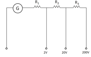
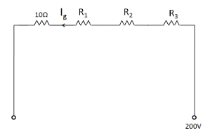
A multi-range voltmeter can be constructed by using a galvanometer circuit as shown in the figure. We want to construct a voltmeter that can measure $ 2{\text{V}} $ , $ 20{\text{V}} $ and $ 200{\text{V}} $ using a galvanometer of resistance $ 10\Omega $ and that produces maximum deflection for current of $ 1{\text{ mA}} $ . Find the value of $ R_1 $ , $ R_2 $ and $ R_3 $ that have to be used.
Answer
570.6k+ views
Hint : To solve this question we have to separately consider each of the three voltmeters. Then, applying the Ohm’s law to each circuit thus obtained, we can get the respective values of the resistances.
Complete step by step answer
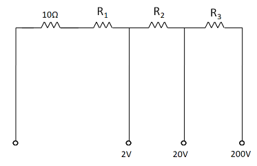
Since the resistance of the galvanometer is given in the question to be equal to $ 10\Omega $ , so the circuit diagram in the question can be redrawn as
Considering the first voltmeter which can be used to measure a voltage of $ 2V $ ,
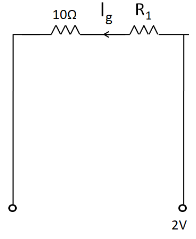
Since the maximum deflection of the galvanometer occurs for a current of $ 1{\text{ mA}} $ , so the current in the circuit is equal to $ 1{\text{ mA}} $ . That is,
$\Rightarrow {I_g} = 1{\text{ mA}} = {10^{ - 3}}{\text{A}} $
The net resistance in the circuit is given by
$\Rightarrow R = 10 + {R_1} $
Also, the voltage across this resistance is equal to $ 2{\text{V}} $ . So from the Ohm’s law we have
$\Rightarrow V = {I_g}R $
$ \Rightarrow 2 = {10^{ - 3}}\left( {10 + {R_1}} \right) $
Multiplying both sides by $ 1000 $
$\Rightarrow {R_1} + 10 = 2000 $
Subtracting $ 10 $ from both the sides we get
$\Rightarrow {R_1} = 1990\Omega $ ……………………………...(1)
Now, we consider the second voltmeter which can measure a voltage of $ 20{\text{V}} $ .
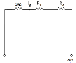
The net resistance in the circuit is
$\Rightarrow R = {R_1} + {R_2} + 10 $
The voltage across the circuit is
$\Rightarrow V = 20{\text{V}} $
So we have
$\Rightarrow 20 = {10^{ - 3}}\left( {{R_1} + {R_2} + 10} \right) $
Multiplying both sides by $ 1000 $
$\Rightarrow {R_1} + {R_2} + 10 = 20000 $
Substituting (1) we get
$\Rightarrow 1990 + {R_2} + 10 = 20000 $
$\Rightarrow {R_2} = 18000\Omega $ ……………………………...(2)
Finally, we consider the second voltmeter which can measure a voltage of $ 200{\text{V}} $ .
The net resistance in the circuit is
$\Rightarrow R = {R_1} + {R_2} + {R_3} + 10 $
The voltage across the circuit is
$\Rightarrow V = 200{\text{V}} $
So we have
$\Rightarrow 200 = {10^{ - 3}}\left( {{R_1} + {R_2} + {R_3} + 10} \right) $
Multiplying both sides by $ 1000 $
$\Rightarrow {R_1} + {R_2} + {R_3} + 10 = 200000 $
Substituting (1) and (2) we get
$\Rightarrow 1990 + 18000 + {R_3} + 10 = 200000 $
$\Rightarrow {R_3} = 180000\Omega $
Hence, the value of $ R_1 $ , $ R_2 $ and $ R_3 $ are $ 1990\Omega $ , $ 18000\Omega $ , and $ 180000\Omega $ respectively.
Note
We should not forget to convert the value of maximum deflection current into the SI unit. Also, the voltage of the left terminal which is connected to the galvanometer is not given. So we have assumed it to be equal to zero volts. This is because then only the voltmeter will measure the respective voltages given in the question.
Complete step by step answer
Since the resistance of the galvanometer is given in the question to be equal to $ 10\Omega $ , so the circuit diagram in the question can be redrawn as
Considering the first voltmeter which can be used to measure a voltage of $ 2V $ ,
Since the maximum deflection of the galvanometer occurs for a current of $ 1{\text{ mA}} $ , so the current in the circuit is equal to $ 1{\text{ mA}} $ . That is,
$\Rightarrow {I_g} = 1{\text{ mA}} = {10^{ - 3}}{\text{A}} $
The net resistance in the circuit is given by
$\Rightarrow R = 10 + {R_1} $
Also, the voltage across this resistance is equal to $ 2{\text{V}} $ . So from the Ohm’s law we have
$\Rightarrow V = {I_g}R $
$ \Rightarrow 2 = {10^{ - 3}}\left( {10 + {R_1}} \right) $
Multiplying both sides by $ 1000 $
$\Rightarrow {R_1} + 10 = 2000 $
Subtracting $ 10 $ from both the sides we get
$\Rightarrow {R_1} = 1990\Omega $ ……………………………...(1)
Now, we consider the second voltmeter which can measure a voltage of $ 20{\text{V}} $ .
The net resistance in the circuit is
$\Rightarrow R = {R_1} + {R_2} + 10 $
The voltage across the circuit is
$\Rightarrow V = 20{\text{V}} $
So we have
$\Rightarrow 20 = {10^{ - 3}}\left( {{R_1} + {R_2} + 10} \right) $
Multiplying both sides by $ 1000 $
$\Rightarrow {R_1} + {R_2} + 10 = 20000 $
Substituting (1) we get
$\Rightarrow 1990 + {R_2} + 10 = 20000 $
$\Rightarrow {R_2} = 18000\Omega $ ……………………………...(2)
Finally, we consider the second voltmeter which can measure a voltage of $ 200{\text{V}} $ .
The net resistance in the circuit is
$\Rightarrow R = {R_1} + {R_2} + {R_3} + 10 $
The voltage across the circuit is
$\Rightarrow V = 200{\text{V}} $
So we have
$\Rightarrow 200 = {10^{ - 3}}\left( {{R_1} + {R_2} + {R_3} + 10} \right) $
Multiplying both sides by $ 1000 $
$\Rightarrow {R_1} + {R_2} + {R_3} + 10 = 200000 $
Substituting (1) and (2) we get
$\Rightarrow 1990 + 18000 + {R_3} + 10 = 200000 $
$\Rightarrow {R_3} = 180000\Omega $
Hence, the value of $ R_1 $ , $ R_2 $ and $ R_3 $ are $ 1990\Omega $ , $ 18000\Omega $ , and $ 180000\Omega $ respectively.
Note
We should not forget to convert the value of maximum deflection current into the SI unit. Also, the voltage of the left terminal which is connected to the galvanometer is not given. So we have assumed it to be equal to zero volts. This is because then only the voltmeter will measure the respective voltages given in the question.
Recently Updated Pages
Master Class 12 Economics: Engaging Questions & Answers for Success
Master Class 12 Physics: Engaging Questions & Answers for Success
Master Class 12 English: Engaging Questions & Answers for Success
Master Class 12 Social Science: Engaging Questions & Answers for Success
Master Class 12 Maths: Engaging Questions & Answers for Success
Master Class 12 Business Studies: Engaging Questions & Answers for Success
Trending doubts
Which are the Top 10 Largest Countries of the World?
What are the major means of transport Explain each class 12 social science CBSE
Draw a labelled sketch of the human eye class 12 physics CBSE
Why cannot DNA pass through cell membranes class 12 biology CBSE
Differentiate between insitu conservation and exsitu class 12 biology CBSE
Draw a neat and well labeled diagram of TS of ovary class 12 biology CBSE