


How is a p-n junction diode used as a half wave rectifier? Explain its working, draw a neat circuit diagram. Show the waveforms of input and output voltages.
Answer
528.5k+ views
Hint: A p-n junction diode can work as an excellent rectifier since it offers a low resistance for the current to flow when it is forward biased; but a very high resistance when reverse biased. Thus, it allows current through it only in one direction and acts as a rectifier.
Complete step by step answer:
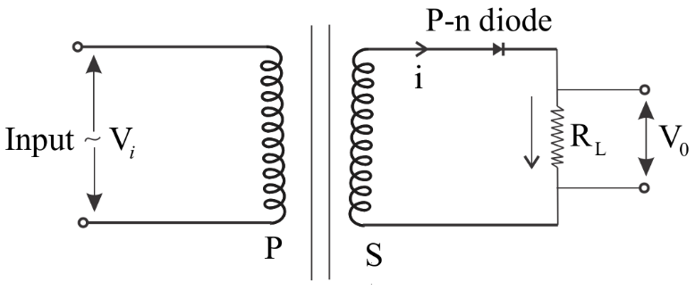
Basically, a rectifier is a device which converts an alternating current into a direct current. A half-wave rectifier consists of a transformer, a diode and a load resistor. The primary coil of the transformer is connected to the ac mains, and the secondary coil to a load resistor $${{\text{R}}_{\text{L}}}$$ through the diode D as shown below in figure: -
The waveforms of input and the corresponding output voltages are as shown below:-
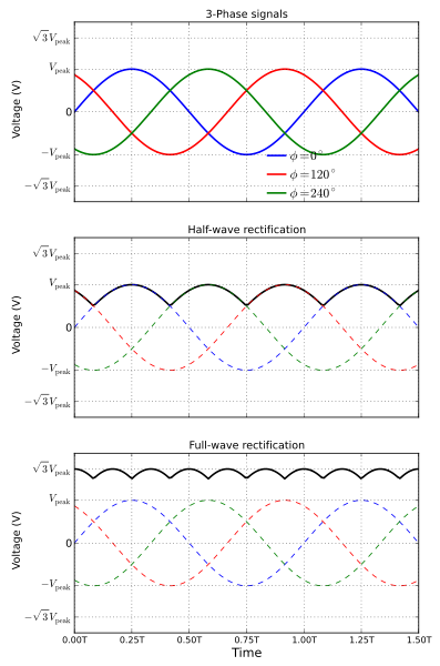
During the positive half-cycle of the input voltage sine wave, the p-n junction diode is forward-biased and hence it conducts through ${{\text{R}}_{\text{L}}}$. The current flowing in the circuit produces a voltage across the load which has the same shape as the positive half-cycle of the input voltage ${{\text{V}}_{\text{i}}}$. During the next half-cycle of the sine wave, the p-n junction diode is reverse-biased. Hence, during this time, no current flows in the circuit and no voltage develops across ${{\text{R}}_{\text{L}}}$. Since only the positive half-cycle of the input appears across the load, the input ac voltage is converted into a pulsating dc voltage. This process is repeated. This process is called Half-Wave Rectification.
Note: The purpose of the transformer is to supply the necessary voltage to the rectifier. It may be a step-up or step-down depending on the requirement. The ratio of RMS value of AC component to DC component in the rectifier is called ripple factor.
Complete step by step answer:
Basically, a rectifier is a device which converts an alternating current into a direct current. A half-wave rectifier consists of a transformer, a diode and a load resistor. The primary coil of the transformer is connected to the ac mains, and the secondary coil to a load resistor $${{\text{R}}_{\text{L}}}$$ through the diode D as shown below in figure: -
The waveforms of input and the corresponding output voltages are as shown below:-
During the positive half-cycle of the input voltage sine wave, the p-n junction diode is forward-biased and hence it conducts through ${{\text{R}}_{\text{L}}}$. The current flowing in the circuit produces a voltage across the load which has the same shape as the positive half-cycle of the input voltage ${{\text{V}}_{\text{i}}}$. During the next half-cycle of the sine wave, the p-n junction diode is reverse-biased. Hence, during this time, no current flows in the circuit and no voltage develops across ${{\text{R}}_{\text{L}}}$. Since only the positive half-cycle of the input appears across the load, the input ac voltage is converted into a pulsating dc voltage. This process is repeated. This process is called Half-Wave Rectification.
Note: The purpose of the transformer is to supply the necessary voltage to the rectifier. It may be a step-up or step-down depending on the requirement. The ratio of RMS value of AC component to DC component in the rectifier is called ripple factor.
Recently Updated Pages
JEE Main 2023 April 6 Shift 1 Question Paper with Answer Key
JEE Main 2023 April 6 Shift 2 Question Paper with Answer Key
JEE Main 2023 (January 31 Evening Shift) Question Paper with Solutions [PDF]
JEE Main 2023 January 30 Shift 2 Question Paper with Answer Key
JEE Main 2023 January 25 Shift 1 Question Paper with Answer Key
JEE Main 2023 January 24 Shift 2 Question Paper with Answer Key
Trending doubts
JEE Main 2026: Session 2 Registration Open, City Intimation Slip, Exam Dates, Syllabus & Eligibility
JEE Main 2026 Application Login: Direct Link, Registration, Form Fill, and Steps
Understanding the Angle of Deviation in a Prism
Hybridisation in Chemistry – Concept, Types & Applications
How to Convert a Galvanometer into an Ammeter or Voltmeter
Understanding Uniform Acceleration in Physics
Other Pages
JEE Advanced Marks vs Ranks 2025: Understanding Category-wise Qualifying Marks and Previous Year Cut-offs
Laws of Motion Class 11 Physics Chapter 4 CBSE Notes - 2025-26
Waves Class 11 Physics Chapter 14 CBSE Notes - 2025-26
Mechanical Properties of Fluids Class 11 Physics Chapter 9 CBSE Notes - 2025-26
Thermodynamics Class 11 Physics Chapter 11 CBSE Notes - 2025-26
Units And Measurements Class 11 Physics Chapter 1 CBSE Notes - 2025-26