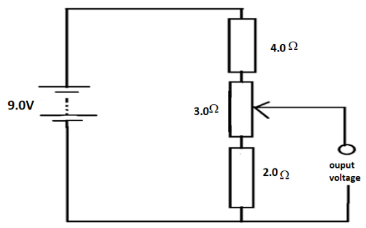
A potential divider circuit consists of fixed resistors of resistance $2.0\Omega $ and $4.0\Omega $ connected in series with a $3.0\Omega $ resistor fitted with a sliding contact. These are connected across a battery of e.m.f $9.0V$ and zero internal resistance, as shown. What are the maximum and the minimum output voltage of this potential divider circuit?


Answer
557.1k+ views
Hint:In this question, we have to find the voltage of this potential divider circuit. Voltage divider circuits are used to produce different voltage levels from common voltage sources but current will remain the same for all components in series circuits.
Complete step by step answer:
Total resistance of the circuit be given by $R = 1.0 + 2.0 + 3.0 = 9.0\Omega $
As resistances are connected in series so we simply add all the values of resistances.
Total voltage across the circuit is given to be $V = 9.0V$
Now applying Ohm’s law to find the current $I = \dfrac{V}{R}$
$I = \dfrac{{9.0}}{{9.0}}A$
$\Rightarrow I = 1A$
Case $1$ : If contact is at the lower position:
Taking only the lower resistance and in this case, we will have the minimum voltage ${V_{\min }} = 2.0 \times 1.0 = 2.0V$
Case $2.$ if contact is at the upper position:
In this case we will consider two resistance and the resultant be given by adding these two i.e.,$\left( {2.0 + 3.0} \right)$
Hence, maximum voltage be given as ${V_{\max }} = 5.0 \times 1.0 = 5.0V$
Hence, the maximum output voltage of this potential divider circuit is $5.0V$ and the minimum output voltage of this potential divider circuit is given by $2.0V$.
Note:We had used the potentiometer which is a variable resistor with a sling contact used in mostly voltage divider circuits. The output voltage is maximum when maximum value of the variable resistor is taken and minimum when the minimum value of variable resistor is taken.
Recently Updated Pages
Master Class 12 Economics: Engaging Questions & Answers for Success

Master Class 12 Physics: Engaging Questions & Answers for Success

Master Class 12 English: Engaging Questions & Answers for Success

Master Class 12 Social Science: Engaging Questions & Answers for Success

Master Class 12 Maths: Engaging Questions & Answers for Success

Master Class 12 Business Studies: Engaging Questions & Answers for Success

Trending doubts
Which are the Top 10 Largest Countries of the World?

What are the major means of transport Explain each class 12 social science CBSE

Draw a labelled sketch of the human eye class 12 physics CBSE

Why cannot DNA pass through cell membranes class 12 biology CBSE

Differentiate between insitu conservation and exsitu class 12 biology CBSE

Draw a neat and well labeled diagram of TS of ovary class 12 biology CBSE


