


A realistic graph depicting the variation of the reciprocal of input resistance in an input characteristics measurement in a common-emitter transistor configuration is:
Answer
571.8k+ views
Hint: In this question first we will understand the basics of common- emitter and also study about basic or resistance. This will help us to make the suitable graph. Further, we will study the basic electrical circuit with diagrams, for our better understanding.
Complete step-by-step answer:
As we know that the common- emitter circuit is mostly used in junction, transistor amplifiers. When compared with the common- base connection, common- emitter has higher input impedance and lower output impedance.
Here, we also know that the resistance is a measure of the opposition to current flow in an electrical circuit. Further, it is measured in Ohms.
Following graph is obtained, as we know that resistance is inversely related to the voltage.

Therefore, we get the required graph showing the variation of the reciprocal of input resistance in an input characteristics measurement in a common-emitter transistor configuration.
Additional Information: Resistance depends upon the shape, size of a material. As we know that a resistance opposes the flow of current in a circuit, so, the resistance in an ammeter should be very small because it should not change the value of the current flowing in the circuit, i.e., current should remain the same it should not vary.
As we know that an ammeter is used to measure the current. The S.I unit of current is Ampere (A). Also, an electric current is a stream of charged particles like electrons, moving through a conductor.
Following is the basic electric circuit diagram having an ammeter, voltmeter, resistance, a key and a battery.
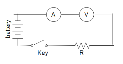
Further, potential (V) is defined as the amount of work needed to move one unit of electric charge from a reference point to a specific point in an electric field. Voltmeter is used to measure electric potential difference between two points in an electric circuit. The S.I unit of potential is Volts (V).
Note: Here, we should know that the Current can be measured in different units like micro Ampere, mili Ampere. Potential can be measured in different units like microVolts, milliVolts. In insulators the flow of current is not possible whereas, in conductors the flow of current is seen which makes it a good conductor of heat and electricity.
Complete step-by-step answer:
As we know that the common- emitter circuit is mostly used in junction, transistor amplifiers. When compared with the common- base connection, common- emitter has higher input impedance and lower output impedance.
Here, we also know that the resistance is a measure of the opposition to current flow in an electrical circuit. Further, it is measured in Ohms.
Following graph is obtained, as we know that resistance is inversely related to the voltage.
Therefore, we get the required graph showing the variation of the reciprocal of input resistance in an input characteristics measurement in a common-emitter transistor configuration.
Additional Information: Resistance depends upon the shape, size of a material. As we know that a resistance opposes the flow of current in a circuit, so, the resistance in an ammeter should be very small because it should not change the value of the current flowing in the circuit, i.e., current should remain the same it should not vary.
As we know that an ammeter is used to measure the current. The S.I unit of current is Ampere (A). Also, an electric current is a stream of charged particles like electrons, moving through a conductor.
Following is the basic electric circuit diagram having an ammeter, voltmeter, resistance, a key and a battery.
Further, potential (V) is defined as the amount of work needed to move one unit of electric charge from a reference point to a specific point in an electric field. Voltmeter is used to measure electric potential difference between two points in an electric circuit. The S.I unit of potential is Volts (V).
Note: Here, we should know that the Current can be measured in different units like micro Ampere, mili Ampere. Potential can be measured in different units like microVolts, milliVolts. In insulators the flow of current is not possible whereas, in conductors the flow of current is seen which makes it a good conductor of heat and electricity.
Recently Updated Pages
Master Class 12 Economics: Engaging Questions & Answers for Success
Master Class 12 Physics: Engaging Questions & Answers for Success
Master Class 12 English: Engaging Questions & Answers for Success
Master Class 12 Social Science: Engaging Questions & Answers for Success
Master Class 12 Maths: Engaging Questions & Answers for Success
Master Class 12 Business Studies: Engaging Questions & Answers for Success
Trending doubts
Which are the Top 10 Largest Countries of the World?
What are the major means of transport Explain each class 12 social science CBSE
Draw a labelled sketch of the human eye class 12 physics CBSE
Why cannot DNA pass through cell membranes class 12 biology CBSE
Differentiate between insitu conservation and exsitu class 12 biology CBSE
Draw a neat and well labeled diagram of TS of ovary class 12 biology CBSE