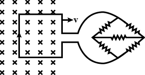
A square metal loop of side $ 20cm $ and resistance $ 2ohm $ is moved with a constant velocity partly inside a uniform magnetic field of $ 5\dfrac{Wb}{{{m}^{2}}} $ , directed into the paper. As shown in the figure, the loop is connected to a network of five resistors each of value $ R $ . If a steady current of $ 0.1A $ flows in the loop and the speed of the loop is $ 1\dfrac{m}{s} $ , then $ R $ is equal to

(A) $ 2\Omega $
(B) $ 3\Omega $
(C) $ 8\Omega $
(D) $ 9\Omega $

Answer
526.8k+ views
Hint: In order to solve this question, we will be using the concept of magnetic flux and the Faraday’s Law of induction. We will also use the relation between the electric current and the magnetic field. We will also use some basic concepts of addition of resistance and Ohm’s law.
Complete step by step answer:
First of all, we will write down the data that is given to us,
The magnitude of the uniform magnetic field is $ B=5\dfrac{Wb}{{{m}^{2}}} $ ,
The resistance of the loop $ r=2ohm $ ,
The vertical length of the metal loop $ L=20cm=0.2m $ ,
The current flowing inside the loop $ i=0.1A $ ,
The velocity of the loop $ v=1\dfrac{m}{s} $ .
The resistance of each resistor in the attached circuit is $ R $ .
If we look at the question, we can see that we are having a metal loop which is parallel to the plane of paper and is moving in the positive-x direction. We can also see that we have a uniform magnetic field which is in a direction that is perpendicular to the plane of paper and is going inwards.
Now, according to Faraday's law of electromagnetic induction, we know that an $ emf $ is induced inside the metal loop if there is a change in magnetic flux passing through the cross sectional area of the loop.
$ emf=-\dfrac{\Delta \Phi }{\Delta t} $
Where $ \Delta \Phi $ is the change in magnetic flux, $ \Delta t $ is the change in time.
The negative sign in the above equation shows that the induced $ emf $ is in the negative direction of that of the change in magnetic flux. This induced $ emf $ results in a current flowing through the loop.
But, as we can see that the magnetic field in the question is uniform and hence the only way the change in the magnetic flux occurs is when the coil is moved in this field which is the case over here. Now, when we move the loop, the cross sectional area also moves across the plane of paper. Therefore, we can write the above equation in terms of area as
$ emf=-\dfrac{B\Delta A}{\Delta t} $
Where $ B $ is the magnetic field and $ \Delta A $ is the change in cross sectional area.
Now, we also can calculate the area swept by the metal coil, i.e., the change in area, as
$ \Delta A=Lv\Delta t $
Therefore, the equation for induced $ emf $ becomes
$ emf=-BLv $
Placing the values in the above equation
$ \begin{align}
& emf=-(5)(0.2)(1) \\
& emf=-1Volt \\
\end{align} $
The magnitude of $ emf $ generated inside the metal loop is $ 1Volt $
Now if we look at the right hand side of the figure, we can see that the circuit is similar to the Wheatstone bridge. The first thing we have to do is to simplify the circuit and to do so, we need to calculate the equivalent resistance of the following circuit.
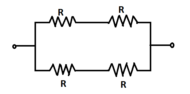
The resistance at the center of the Wheatstone bridge is neglected as there is no current passing through this resistance when the bridge is in balanced condition. Therefore the remaining four resistance can be interpreted as two series of two resistances connected in parallel to each other.

Now, calculating the equivalent resistance for this circuit, the upper and the lower series will have a resistance of $ 2R $ respectively and then the equivalent resistance of the whole circuit will be
$ \begin{align}
& \dfrac{1}{{{R}_{eq}}}=\dfrac{1}{2R}+\dfrac{1}{2R}=\dfrac{1}{R} \\
& \Rightarrow {{R}_{eq}}=R \\
\end{align} $
Now the loop and the circuit are in series with each other hence, the final equilibrium resistance of the loop is
$ \begin{align}
& {{R}_{EQ}}={{R}_{eq}}+r \\
& {{R}_{EQ}}=R+2 \\
\end{align} $
Using the Ohm’s law, the voltage across the whole circuit
$ V=i{{R}_{EQ}} $
We can now say that the induced $ emf $ that is generated in the loop is equivalent to the voltage across the whole circuit containing the loop. Therefore,
$ \begin{align}
& emf=V \\
& emf=i{{R}_{EQ}} \\
\end{align} $
We know the values of the current and the induced $ emf $ . Placing the values and $ {{R}_{EQ}}=R+2 $
$ \begin{align}
& \Rightarrow 1=(0.1)(R+2) \\
& \Rightarrow R+2=10 \\
& \Rightarrow R=8\Omega \\
\end{align} $
Therefore, the answer to our question is option(C).
Note:
Don’t forget to consider the internal resistance of the connecting wires in the circuit and the loop. In this case, the internal resistance of the loop is $ 2\Omega $ and that of the connecting wires in the attached circuit is taken to be negligible.
Complete step by step answer:
First of all, we will write down the data that is given to us,
The magnitude of the uniform magnetic field is $ B=5\dfrac{Wb}{{{m}^{2}}} $ ,
The resistance of the loop $ r=2ohm $ ,
The vertical length of the metal loop $ L=20cm=0.2m $ ,
The current flowing inside the loop $ i=0.1A $ ,
The velocity of the loop $ v=1\dfrac{m}{s} $ .
The resistance of each resistor in the attached circuit is $ R $ .
If we look at the question, we can see that we are having a metal loop which is parallel to the plane of paper and is moving in the positive-x direction. We can also see that we have a uniform magnetic field which is in a direction that is perpendicular to the plane of paper and is going inwards.
Now, according to Faraday's law of electromagnetic induction, we know that an $ emf $ is induced inside the metal loop if there is a change in magnetic flux passing through the cross sectional area of the loop.
$ emf=-\dfrac{\Delta \Phi }{\Delta t} $
Where $ \Delta \Phi $ is the change in magnetic flux, $ \Delta t $ is the change in time.
The negative sign in the above equation shows that the induced $ emf $ is in the negative direction of that of the change in magnetic flux. This induced $ emf $ results in a current flowing through the loop.
But, as we can see that the magnetic field in the question is uniform and hence the only way the change in the magnetic flux occurs is when the coil is moved in this field which is the case over here. Now, when we move the loop, the cross sectional area also moves across the plane of paper. Therefore, we can write the above equation in terms of area as
$ emf=-\dfrac{B\Delta A}{\Delta t} $
Where $ B $ is the magnetic field and $ \Delta A $ is the change in cross sectional area.
Now, we also can calculate the area swept by the metal coil, i.e., the change in area, as
$ \Delta A=Lv\Delta t $
Therefore, the equation for induced $ emf $ becomes
$ emf=-BLv $
Placing the values in the above equation
$ \begin{align}
& emf=-(5)(0.2)(1) \\
& emf=-1Volt \\
\end{align} $
The magnitude of $ emf $ generated inside the metal loop is $ 1Volt $
Now if we look at the right hand side of the figure, we can see that the circuit is similar to the Wheatstone bridge. The first thing we have to do is to simplify the circuit and to do so, we need to calculate the equivalent resistance of the following circuit.
The resistance at the center of the Wheatstone bridge is neglected as there is no current passing through this resistance when the bridge is in balanced condition. Therefore the remaining four resistance can be interpreted as two series of two resistances connected in parallel to each other.

Now, calculating the equivalent resistance for this circuit, the upper and the lower series will have a resistance of $ 2R $ respectively and then the equivalent resistance of the whole circuit will be
$ \begin{align}
& \dfrac{1}{{{R}_{eq}}}=\dfrac{1}{2R}+\dfrac{1}{2R}=\dfrac{1}{R} \\
& \Rightarrow {{R}_{eq}}=R \\
\end{align} $
Now the loop and the circuit are in series with each other hence, the final equilibrium resistance of the loop is
$ \begin{align}
& {{R}_{EQ}}={{R}_{eq}}+r \\
& {{R}_{EQ}}=R+2 \\
\end{align} $
Using the Ohm’s law, the voltage across the whole circuit
$ V=i{{R}_{EQ}} $
We can now say that the induced $ emf $ that is generated in the loop is equivalent to the voltage across the whole circuit containing the loop. Therefore,
$ \begin{align}
& emf=V \\
& emf=i{{R}_{EQ}} \\
\end{align} $
We know the values of the current and the induced $ emf $ . Placing the values and $ {{R}_{EQ}}=R+2 $
$ \begin{align}
& \Rightarrow 1=(0.1)(R+2) \\
& \Rightarrow R+2=10 \\
& \Rightarrow R=8\Omega \\
\end{align} $
Therefore, the answer to our question is option(C).
Note:
Don’t forget to consider the internal resistance of the connecting wires in the circuit and the loop. In this case, the internal resistance of the loop is $ 2\Omega $ and that of the connecting wires in the attached circuit is taken to be negligible.
Recently Updated Pages
Master Class 12 Economics: Engaging Questions & Answers for Success

Master Class 12 Physics: Engaging Questions & Answers for Success

Master Class 12 English: Engaging Questions & Answers for Success

Master Class 12 Social Science: Engaging Questions & Answers for Success

Master Class 12 Maths: Engaging Questions & Answers for Success

Master Class 12 Business Studies: Engaging Questions & Answers for Success

Trending doubts
Which are the Top 10 Largest Countries of the World?

What are the major means of transport Explain each class 12 social science CBSE

Draw a labelled sketch of the human eye class 12 physics CBSE

Why cannot DNA pass through cell membranes class 12 biology CBSE

Differentiate between insitu conservation and exsitu class 12 biology CBSE

Draw a neat and well labeled diagram of TS of ovary class 12 biology CBSE


