


(a) State the working principle of the potentiometer. Explain with the help of a circuit diagram, how the potentiometer is used to determine the internal resistance of the given primary cell.
(b) A battery of emf 10V and internal resistance \[3\Omega \] s connected to a resistor R. If the current in the circuit is 0.5A, calculate the value of R.
Answer
571.2k+ views
Hint: We should understand the different theorems involved in the electric circuit analysis. The potentiometer is a useful instrument, which works on the principle of Kirchhoff’s loop rule condition usually to measure the emf of different sources. We have to discuss the condition thoroughly.
Complete step by step solution:
A potentiometer is an instrument which is used in the laboratories to get an accurate measure of the emf or the internal resistance of a primary cell. According to Kirchhoff's loop rule, the algebraic sum of the changes in the potential differences in a closed loop with resistors and cells will be always zero.
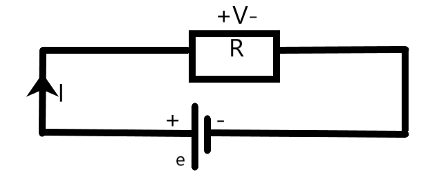
We can see from the above simple circuit that –
\[\begin{align}
& \varepsilon -V=0 \\
& \Rightarrow \varepsilon -IR=0 \\
\end{align}\]
This is one of the leading principles in a potentiometer.
A potentiometer consists of a long uniformly thick metallic wire extending to a few meters. The wire is connected to an external power supply and to the cell whose parameters we need to measure.
We need to consider a quantity known as the potential drop per unit length. It is the potential drop at any unit length of the wire whose length is L. It is given as –
\[\begin{align}
& \phi =\dfrac{\varepsilon }{L} \\
& \Rightarrow \varepsilon =\phi L \\
\end{align}\]
To measure the internal resistance of a cell of emf \[\varepsilon \], we can use the circuit as shown below.
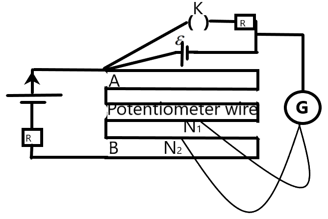
When the Key K is opened, we can obtain the balance at the length \[{{L}_{1}}\] as –
\[\varepsilon =\phi {{L}_{1}}\text{ --(1)}\]
Now, we close the key K and we get the potential difference across the cell when the balance is obtained at \[{{L}_{2}}\] as –
\[V=\phi {{L}_{2}}\text{ --(2)}\]
We can take the ratio between the emf and the potential drop in the two cases as –
\[\dfrac{\varepsilon }{V}=\dfrac{{{L}_{1}}}{{{L}_{2}}}\]
But we know that the emf can be equated as –
\[\begin{align}
& \varepsilon =I(r+R) \\
& \text{and,} \\
& V=IR \\
\end{align}\]
Using this information, we can solve for the internal resistance r as –
\[\begin{align}
& \dfrac{\varepsilon }{V}=\dfrac{I(r+R)}{IR}=\dfrac{{{L}_{1}}}{{{L}_{2}}} \\
& \Rightarrow \dfrac{(r+R)}{R}=\dfrac{{{L}_{1}}}{{{L}_{2}}} \\
& \therefore r=R(\dfrac{{{L}_{1}}}{{{L}_{2}}}-1) \\
\end{align}\]
This gives the internal resistance of the primary cell using the potentiometer.
(b) We are given a circuit with a resistor which is connected to an external voltage of 10 V and an internal resistance of \[3\Omega \] and a current 0.5 A through the resistor. We can easily find the resistance of the resistor by using the formula –
\[\begin{align}
& I=\dfrac{\varepsilon }{R+r} \\
& \Rightarrow IR+Ir=\varepsilon \\
& \Rightarrow R=\dfrac{\varepsilon -Ir}{I} \\
& \Rightarrow R=\dfrac{10-(0.5)(3)}{0.5} \\
& \therefore R=17\Omega \\
\end{align}\]
The resistance of the resistor used in the circuit will be 17 \[\Omega \].
This is the required solution.
Note: We find the electromotive force of the primary cells by comparing two of the primary cells using a potentiometer. The instrument has higher accuracy due to the fact that it doesn’t extract emf from the cells under consideration for working, which is a disadvantage of the voltmeters.
Complete step by step solution:
A potentiometer is an instrument which is used in the laboratories to get an accurate measure of the emf or the internal resistance of a primary cell. According to Kirchhoff's loop rule, the algebraic sum of the changes in the potential differences in a closed loop with resistors and cells will be always zero.
We can see from the above simple circuit that –
\[\begin{align}
& \varepsilon -V=0 \\
& \Rightarrow \varepsilon -IR=0 \\
\end{align}\]
This is one of the leading principles in a potentiometer.
A potentiometer consists of a long uniformly thick metallic wire extending to a few meters. The wire is connected to an external power supply and to the cell whose parameters we need to measure.
We need to consider a quantity known as the potential drop per unit length. It is the potential drop at any unit length of the wire whose length is L. It is given as –
\[\begin{align}
& \phi =\dfrac{\varepsilon }{L} \\
& \Rightarrow \varepsilon =\phi L \\
\end{align}\]
To measure the internal resistance of a cell of emf \[\varepsilon \], we can use the circuit as shown below.
When the Key K is opened, we can obtain the balance at the length \[{{L}_{1}}\] as –
\[\varepsilon =\phi {{L}_{1}}\text{ --(1)}\]
Now, we close the key K and we get the potential difference across the cell when the balance is obtained at \[{{L}_{2}}\] as –
\[V=\phi {{L}_{2}}\text{ --(2)}\]
We can take the ratio between the emf and the potential drop in the two cases as –
\[\dfrac{\varepsilon }{V}=\dfrac{{{L}_{1}}}{{{L}_{2}}}\]
But we know that the emf can be equated as –
\[\begin{align}
& \varepsilon =I(r+R) \\
& \text{and,} \\
& V=IR \\
\end{align}\]
Using this information, we can solve for the internal resistance r as –
\[\begin{align}
& \dfrac{\varepsilon }{V}=\dfrac{I(r+R)}{IR}=\dfrac{{{L}_{1}}}{{{L}_{2}}} \\
& \Rightarrow \dfrac{(r+R)}{R}=\dfrac{{{L}_{1}}}{{{L}_{2}}} \\
& \therefore r=R(\dfrac{{{L}_{1}}}{{{L}_{2}}}-1) \\
\end{align}\]
This gives the internal resistance of the primary cell using the potentiometer.
(b) We are given a circuit with a resistor which is connected to an external voltage of 10 V and an internal resistance of \[3\Omega \] and a current 0.5 A through the resistor. We can easily find the resistance of the resistor by using the formula –
\[\begin{align}
& I=\dfrac{\varepsilon }{R+r} \\
& \Rightarrow IR+Ir=\varepsilon \\
& \Rightarrow R=\dfrac{\varepsilon -Ir}{I} \\
& \Rightarrow R=\dfrac{10-(0.5)(3)}{0.5} \\
& \therefore R=17\Omega \\
\end{align}\]
The resistance of the resistor used in the circuit will be 17 \[\Omega \].
This is the required solution.
Note: We find the electromotive force of the primary cells by comparing two of the primary cells using a potentiometer. The instrument has higher accuracy due to the fact that it doesn’t extract emf from the cells under consideration for working, which is a disadvantage of the voltmeters.
Recently Updated Pages
Master Class 12 Economics: Engaging Questions & Answers for Success
Master Class 12 Physics: Engaging Questions & Answers for Success
Master Class 12 English: Engaging Questions & Answers for Success
Master Class 12 Social Science: Engaging Questions & Answers for Success
Master Class 12 Maths: Engaging Questions & Answers for Success
Master Class 12 Business Studies: Engaging Questions & Answers for Success
Trending doubts
Which are the Top 10 Largest Countries of the World?
What are the major means of transport Explain each class 12 social science CBSE
Draw a labelled sketch of the human eye class 12 physics CBSE
Differentiate between insitu conservation and exsitu class 12 biology CBSE
Draw a neat and well labeled diagram of TS of ovary class 12 biology CBSE
Give 10 examples of unisexual and bisexual flowers