


(a) what are logic gates?
(b) Draw a circuit diagram for dual-input AND Gate by using two diodes.
Answer
595.8k+ views
Hint: It is a logical statement. Logic gate has only two discrete values. There is only a level for voltage. No intermediate voltage is accessed between maximum and minimum. It is opposite to analogue quantities. In daily life we used devices based on this logic.
Complete step by step solution:
(a) What are logic gates?
We all know that devices which have a continuous form such as amplifiers etc. such quantities are known as analogue quantities. But the calculator we use or computer are the devices which operate on discrete voltage levels. There are only two possibilities, in this kind of level either high or low. There are the only two discrete values which are used. The LOW level is represented as ‘0’ and HIGH level is represented as ‘1’. It means the discrete voltage level has only two numbers by which it is represented. Those are 0 and 1. The number system which has only two values is called a binary number system. The circuits which are based on binary numbers are called digital circuits.
The logic functions are used in designing digital systems. The logic functions used are AND, OR, NOT, NAND, NOR etc. Electronic circuits consist of circuits which have transistors, resistors, diodes which perform those logic functions. Logic gates are basic building blocks of all digital systems. AND, OR and NOT gates are called basic gates.
(b) Draw a circuit diagram for dual-input AND Gate by using two diodes.
The logic gate may contain more than one input and it will have only one output. The value of input and output may be 0 or 1.
Operations performed in the logic gate can be represented in the truth table.
AND GATE: it is an electronic circuit which may have more than one input and only one output. It produces high output when all the numerical values will be 1 and elsewhere it is 0.
Circuit diagram for dual-input AND Gate by using two diodes:
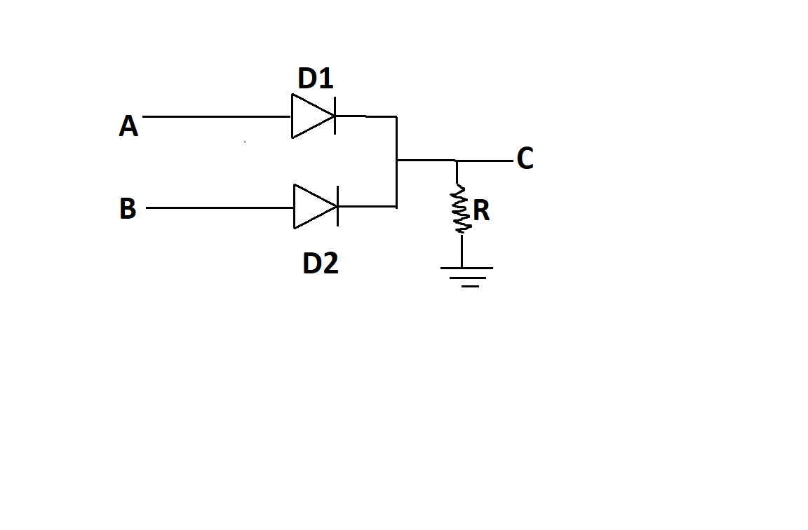
Where,
a and b are inputs
R= resistance
c=output
D1 and D2 are diodes
Note: Operations used in logic gates are thought process and represented by mathematical expression. Logical algebras used are known as Boolean algebra. Variables and expressions used in logic gates are only 0 and 1.
Complete step by step solution:
(a) What are logic gates?
We all know that devices which have a continuous form such as amplifiers etc. such quantities are known as analogue quantities. But the calculator we use or computer are the devices which operate on discrete voltage levels. There are only two possibilities, in this kind of level either high or low. There are the only two discrete values which are used. The LOW level is represented as ‘0’ and HIGH level is represented as ‘1’. It means the discrete voltage level has only two numbers by which it is represented. Those are 0 and 1. The number system which has only two values is called a binary number system. The circuits which are based on binary numbers are called digital circuits.
The logic functions are used in designing digital systems. The logic functions used are AND, OR, NOT, NAND, NOR etc. Electronic circuits consist of circuits which have transistors, resistors, diodes which perform those logic functions. Logic gates are basic building blocks of all digital systems. AND, OR and NOT gates are called basic gates.
(b) Draw a circuit diagram for dual-input AND Gate by using two diodes.
The logic gate may contain more than one input and it will have only one output. The value of input and output may be 0 or 1.
Operations performed in the logic gate can be represented in the truth table.
AND GATE: it is an electronic circuit which may have more than one input and only one output. It produces high output when all the numerical values will be 1 and elsewhere it is 0.
Circuit diagram for dual-input AND Gate by using two diodes:
Where,
a and b are inputs
R= resistance
c=output
D1 and D2 are diodes
Note: Operations used in logic gates are thought process and represented by mathematical expression. Logical algebras used are known as Boolean algebra. Variables and expressions used in logic gates are only 0 and 1.
Recently Updated Pages
Master Class 12 Economics: Engaging Questions & Answers for Success
Master Class 12 Physics: Engaging Questions & Answers for Success
Master Class 12 English: Engaging Questions & Answers for Success
Master Class 12 Social Science: Engaging Questions & Answers for Success
Master Class 12 Maths: Engaging Questions & Answers for Success
Master Class 12 Business Studies: Engaging Questions & Answers for Success
Trending doubts
Which are the Top 10 Largest Countries of the World?
What are the major means of transport Explain each class 12 social science CBSE
Draw a labelled sketch of the human eye class 12 physics CBSE
Differentiate between insitu conservation and exsitu class 12 biology CBSE
Draw a neat and well labeled diagram of TS of ovary class 12 biology CBSE
Give 10 examples of unisexual and bisexual flowers