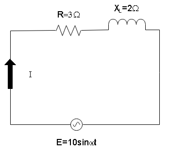
An A.C circuit having supply voltage $ E $ consists of a resistor of resistance $ 3\;\Omega $ and an inductor of reactance $ 4\;\Omega $ as shown in the figure. The voltage across the inductor at $ t = \mu \;/\omega $ is

A) 2 volts
B) 10 volts
C) zero
D) $ 4.8 $ volts

Answer
564.9k+ views
Hint: In this solution, we will determine the net impedance of the circuit using the relation for the series LCR circuit. Then we will use the relation of current and impedance to find the voltage across the inductor.
Formula used: In this solution, we will use the following formula:
- Magnitude of Impedance of a series LCR circuit: $ \left| z \right| = \sqrt {{R^2} + {{\left( {X_L^2 - X_C^2} \right)}^2}} $ where $ R $ is the resistance, $ {X_L} $ is the inductive impedance, and $ {X_C} $ is the capacitive inductance.
Complete step by step answer
In the circuit given to us we can see that a capacitor and a resistor are connected in series with an A.C. power supply such that the resistance is $ 3\;\Omega $ and the inductor of reactance $ 4\;\Omega $ . Then the net impedance of the circuit will be
$ \left| z \right| = \sqrt {{R^2} + X_L^2} $
$ \Rightarrow \left| z \right| = \sqrt {{3^2} + {4^2}} $
Which gives us
$ \left| z \right| = 5\,\Omega $
Now the voltage of the AC supply is $ E = 10\sin \omega t $ . So, at time $ t = \mu \;/\omega $ , the external voltage will be
$ E = 10\sin \left( {\omega \dfrac{\mu }{\omega }} \right) $
$ \Rightarrow E = 10\sin \mu $
Now the current across the inductor can be calculated as
$ {i_L} = \dfrac{E}{{{X_L}}} $
Which gives us
$ {i_L} = \dfrac{{10\sin \mu }}{4} $
Now since $ \sin \mu = \sin {10^{ - 6}} \to 0 $ , the potential across the inductor will also be zero.
Hence the correct choice is option (C).
Note
The reason the potential drop across the inductor will be zero since that, at this point, the inductor will have been completely discharged assuming it was initially discharged. So, if the external potential increases, the inductor will oppose the change in current and induce its own potential, thereby allowing no current to flow in the circuit. The trick in this question hence is to observe the time period at which we want to calculate the potential difference is just at the beginning of the time period of oscillation of alternating frequency.
Recently Updated Pages
Master Class 12 Economics: Engaging Questions & Answers for Success

Master Class 12 Physics: Engaging Questions & Answers for Success

Master Class 12 English: Engaging Questions & Answers for Success

Master Class 12 Social Science: Engaging Questions & Answers for Success

Master Class 12 Maths: Engaging Questions & Answers for Success

Master Class 12 Business Studies: Engaging Questions & Answers for Success

Trending doubts
Which are the Top 10 Largest Countries of the World?

What are the major means of transport Explain each class 12 social science CBSE

Draw a labelled sketch of the human eye class 12 physics CBSE

Why cannot DNA pass through cell membranes class 12 biology CBSE

Differentiate between insitu conservation and exsitu class 12 biology CBSE

Draw a neat and well labeled diagram of TS of ovary class 12 biology CBSE


