


An L-C-R series circuit with a resistance of \[100\Omega \] is connected to 200V (AC source) and angular frequency 300 rad/s. When only the capacitor is removed, then the current lags behind the voltage by \[{{60}^{\circ }}.\] When only the inductor is removed the current leads the voltage by \[{{60}^{\circ }}.\] The average power dissipated in the original L-C-R circuit is:
(a) 50 W
(b) 100 W
(c) 200 W
(d) 400 W
Answer
585.3k+ views
Hint: An L-C-R circuit can be expressed as (in simple words) a circuit having an inductor, resistance and capacitor. We use the phasor diagram to get the relation between the inductance and reactance from which the resonance condition can be proved. Then we will use the condition of resonance to get the value of current. Power dissipation is a product of current, voltage and cosine of the angle between them. Then we will put the values and get the value of power dissipation.
Formulas used:
\[\text{Power Dissipated}=\text{Current }\times \text{ Voltage }\times \text{ cos}\phi \]
Complete step by step answer:
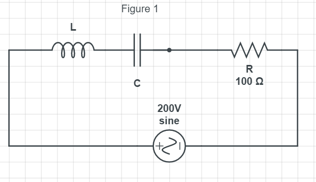
We have been provided with an L-C-R series circuit having a resistance of \[100\Omega \] which is connected to an AC source of 200 V. The angular frequency is given as,
\[\omega =300rad/s\]
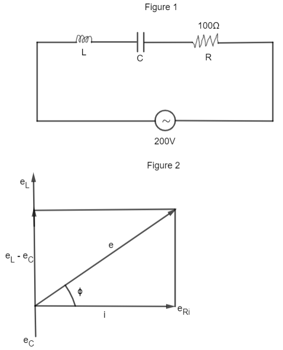
From the phasor diagram shown in figure (1), the current lags voltage by an angle \[\phi \] which is given by
\[\tan \phi =\dfrac{{{e}_{L}}-{{e}_{C}}}{{{e}_{R}}}\]
We know that e = iz, so we get,
\[\tan \phi =\dfrac{{{X}_{L}}-{{X}_{C}}}{R}.....\left( i \right)\]
Now, we have given that, when the capacitance is removed, the current lags behind the voltage by \[{{60}^{\circ }},\] i.e, \[{{X}_{C}}=0.\]
So, equation (i) can be written as,
\[\tan \phi =\dfrac{{{X}_{L}}}{R}=\tan {{60}^{\circ }}\]
\[\Rightarrow \tan {{60}^{\circ }}=\dfrac{{{X}_{L}}}{R}\]
\[\Rightarrow {{X}_{L}}=\sqrt{3}R......\left( ii \right)\]
This is the second case when the inductance is removed the current leads the voltage by \[{{60}^{\circ }},\] i.e. \[{{X}_{L}}=0.\]
Therefore, the equation (i) can be written as
\[\tan \phi =\dfrac{{{X}_{C}}}{R}\]
\[\Rightarrow \tan {{60}^{\circ }}=\dfrac{{{X}_{C}}}{R}\]
\[\Rightarrow {{X}_{C}}=\sqrt{3}R......\left( iii \right)\]
So, from equation (ii) and (iii), we can write as,
\[{{X}_{C}}={{X}_{L}}\]
We know that the above expression resembles the resonance.
In the AC circuit with an inductor and capacitor, when the frequency of AC is gradually changed at a certain frequency, the impedance becomes maximum or minimum. This condition is called resonance. And we know that if the frequency of the applied voltage is adjusted so that at a particular frequency, \[{{X}_{C}}={{X}_{L}}\] then Z = R.
Now, let’s calculate the value of power dissipation which is given as,
\[P={{I}_{rms}}\times {{V}_{rms}}\cos \phi \]
where, \[\cos \phi =\dfrac{R}{Z}\]
To calculate the value of \[{{I}_{rms}}:\]
The formula of \[{{I}_{rms}}\] is given by
\[{{I}_{rms}}=\dfrac{{{V}_{rms}}}{Z}\]
(Since Z = R, according to resonance condition)
\[\Rightarrow {{I}_{rms}}=\dfrac{200}{100}\]
\[\Rightarrow {{I}_{rms}}=2A\]
Therefore, the power dissipation is given as
\[P=2\times 200\times \dfrac{R}{Z}\]
\[\Rightarrow P=400\times \dfrac{100}{100}\left( \because R=Z \right)\]
\[\Rightarrow P=400W\]
Hence the average power dissipated in the original L-C-R circuit is 400 W.
Therefore, option (d) is the right answer.
Additional Information:
There are two types of resonant circuits: series and parallel. When the alternating current of different frequencies is sent through a series resonant circuit, it offers minimum impedance and high impedance, i.e. the circuit accepts the only current of resonant frequency and rejects the current of other frequencies. Therefore, it is called an acceptor circuit.
Whereas in the parallel resonant circuit, it rejects the current of the resonant frequency but allows the current of the other frequencies to pass through it, hence called the rejector circuit.
Note:
The resistance property of any kind of the circuit which is responsible for the consumption of electric power as heat, while a pure inductor and pure capacitor does not consume any electric power i.e. no heat is produced. Dependence of reactance is on the frequency of the alternating source, while resistance doesn’t depend on the frequency of the source.
Formulas used:
\[\text{Power Dissipated}=\text{Current }\times \text{ Voltage }\times \text{ cos}\phi \]
Complete step by step answer:
We have been provided with an L-C-R series circuit having a resistance of \[100\Omega \] which is connected to an AC source of 200 V. The angular frequency is given as,
\[\omega =300rad/s\]
From the phasor diagram shown in figure (1), the current lags voltage by an angle \[\phi \] which is given by
\[\tan \phi =\dfrac{{{e}_{L}}-{{e}_{C}}}{{{e}_{R}}}\]
We know that e = iz, so we get,
\[\tan \phi =\dfrac{{{X}_{L}}-{{X}_{C}}}{R}.....\left( i \right)\]
Now, we have given that, when the capacitance is removed, the current lags behind the voltage by \[{{60}^{\circ }},\] i.e, \[{{X}_{C}}=0.\]
So, equation (i) can be written as,
\[\tan \phi =\dfrac{{{X}_{L}}}{R}=\tan {{60}^{\circ }}\]
\[\Rightarrow \tan {{60}^{\circ }}=\dfrac{{{X}_{L}}}{R}\]
\[\Rightarrow {{X}_{L}}=\sqrt{3}R......\left( ii \right)\]
This is the second case when the inductance is removed the current leads the voltage by \[{{60}^{\circ }},\] i.e. \[{{X}_{L}}=0.\]
Therefore, the equation (i) can be written as
\[\tan \phi =\dfrac{{{X}_{C}}}{R}\]
\[\Rightarrow \tan {{60}^{\circ }}=\dfrac{{{X}_{C}}}{R}\]
\[\Rightarrow {{X}_{C}}=\sqrt{3}R......\left( iii \right)\]
So, from equation (ii) and (iii), we can write as,
\[{{X}_{C}}={{X}_{L}}\]
We know that the above expression resembles the resonance.
In the AC circuit with an inductor and capacitor, when the frequency of AC is gradually changed at a certain frequency, the impedance becomes maximum or minimum. This condition is called resonance. And we know that if the frequency of the applied voltage is adjusted so that at a particular frequency, \[{{X}_{C}}={{X}_{L}}\] then Z = R.
Now, let’s calculate the value of power dissipation which is given as,
\[P={{I}_{rms}}\times {{V}_{rms}}\cos \phi \]
where, \[\cos \phi =\dfrac{R}{Z}\]
To calculate the value of \[{{I}_{rms}}:\]
The formula of \[{{I}_{rms}}\] is given by
\[{{I}_{rms}}=\dfrac{{{V}_{rms}}}{Z}\]
(Since Z = R, according to resonance condition)
\[\Rightarrow {{I}_{rms}}=\dfrac{200}{100}\]
\[\Rightarrow {{I}_{rms}}=2A\]
Therefore, the power dissipation is given as
\[P=2\times 200\times \dfrac{R}{Z}\]
\[\Rightarrow P=400\times \dfrac{100}{100}\left( \because R=Z \right)\]
\[\Rightarrow P=400W\]
Hence the average power dissipated in the original L-C-R circuit is 400 W.
Therefore, option (d) is the right answer.
Additional Information:
There are two types of resonant circuits: series and parallel. When the alternating current of different frequencies is sent through a series resonant circuit, it offers minimum impedance and high impedance, i.e. the circuit accepts the only current of resonant frequency and rejects the current of other frequencies. Therefore, it is called an acceptor circuit.
Whereas in the parallel resonant circuit, it rejects the current of the resonant frequency but allows the current of the other frequencies to pass through it, hence called the rejector circuit.
Note:
The resistance property of any kind of the circuit which is responsible for the consumption of electric power as heat, while a pure inductor and pure capacitor does not consume any electric power i.e. no heat is produced. Dependence of reactance is on the frequency of the alternating source, while resistance doesn’t depend on the frequency of the source.
Recently Updated Pages
Master Class 12 Economics: Engaging Questions & Answers for Success
Master Class 12 Physics: Engaging Questions & Answers for Success
Master Class 12 English: Engaging Questions & Answers for Success
Master Class 12 Social Science: Engaging Questions & Answers for Success
Master Class 12 Maths: Engaging Questions & Answers for Success
Master Class 12 Business Studies: Engaging Questions & Answers for Success
Trending doubts
Which are the Top 10 Largest Countries of the World?
What are the major means of transport Explain each class 12 social science CBSE
Draw a labelled sketch of the human eye class 12 physics CBSE
Why cannot DNA pass through cell membranes class 12 biology CBSE
Differentiate between insitu conservation and exsitu class 12 biology CBSE
Draw a neat and well labeled diagram of TS of ovary class 12 biology CBSE