


Derive the formula for the force acting between two parallel current carrying conductors.
Answer
564.6k+ views
Hint: Before we proceed to derive the expression for force acting between two current carrying parallel conductors, we should be familiar with the expression for the Biot-Savart’s law which gives the expression for magnetic field at a point due to a current carrying conductor, as follows –
$dB = \dfrac{{{\mu _0}}}{{4\pi }}\dfrac{{I \cdot dl}}{{{r^3}}}$
where I = current in the circuit, $dl$= length of the current element, r = distance of the point from the current element.
Complete step by step solution:
Consider two conductors A and B of infinite length, with currents ${I_A}$ and ${I_B}$ in the same direction and separated at a distance of d, as shown:
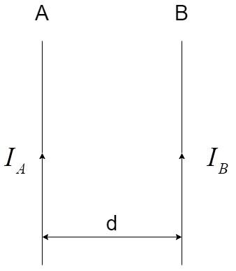
The current ${I_A}$ results in a magnetic field ${B_A}$ at the conductor B, at the distance of d, which is given by applying the Biot-Savart’s law for a conductor carrying current.
${B_A} = \dfrac{{{\mu _0}}}{{4\pi }}\dfrac{{2{I_A}}}{d}$
Whenever a current carrying conductor is placed in an external magnetic field, there is a force acting on it and the force experienced by the conductor is equal to the product of magnetic field, current and the length of the conductor.
$F = BIL$
The conductor B experiences force due to the magnetic field produced by the conductor A, which is given by ${B_A}$.
Therefore, the force acting on the conductor B will be equal to –
$\Rightarrow F = {B_A}{I_B}L$
Substituting the value ${B_A}$ , we have –
$\Rightarrow F = \dfrac{{{\mu _0}}}{{4\pi }}\dfrac{{2{I_A}{I_B}}}{d}L$
Therefore, the force per unit length between two parallel conductors is given by the expression:
$\Rightarrow f = \dfrac{F}{L} = \dfrac{{{\mu _0}}}{{4\pi }}\dfrac{{2{I_A}{I_B}}}{d}$
The direction of the force can be calculated by using the Fleming’s Left Hand rule where:
i) Index finger represents the direction of the magnetic field, B
ii) Middle finger represents the direction of the current, I
iii) Thumb represents the direction of the force, F
The direction of the force is represented in the diagram below:
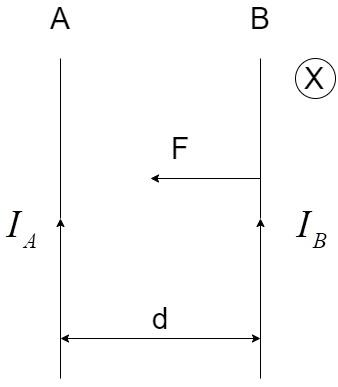
Here, the direction of ${B_A}$is calculated by the Right-Hand screw rule, which gives the result that the direction of the magnetic field is inside the plane of paper and denoted by X.
Note: The standard definition of the SI unit of current, ampere is defined by the help of the derived expression as follows:
If ${I_A} = {I_B} = 1A$ and $d = 1m$, we have –
$\Rightarrow f = \dfrac{{{\mu _0}}}{{4\pi }}\dfrac{{2{I_A}{I_B}}}{d} = {10^{ - 7}} \times \dfrac{{2 \times 1 \times 1}}{1} = 2 \times {10^{ - 7}}N$
Thus, One ampere is defined as the steady current, which when maintained between two infinitely long conductors with unit separation, would produce a force per unit length equal to $2 \times {10^{ - 7}}N$.
$dB = \dfrac{{{\mu _0}}}{{4\pi }}\dfrac{{I \cdot dl}}{{{r^3}}}$
where I = current in the circuit, $dl$= length of the current element, r = distance of the point from the current element.
Complete step by step solution:
Consider two conductors A and B of infinite length, with currents ${I_A}$ and ${I_B}$ in the same direction and separated at a distance of d, as shown:
The current ${I_A}$ results in a magnetic field ${B_A}$ at the conductor B, at the distance of d, which is given by applying the Biot-Savart’s law for a conductor carrying current.
${B_A} = \dfrac{{{\mu _0}}}{{4\pi }}\dfrac{{2{I_A}}}{d}$
Whenever a current carrying conductor is placed in an external magnetic field, there is a force acting on it and the force experienced by the conductor is equal to the product of magnetic field, current and the length of the conductor.
$F = BIL$
The conductor B experiences force due to the magnetic field produced by the conductor A, which is given by ${B_A}$.
Therefore, the force acting on the conductor B will be equal to –
$\Rightarrow F = {B_A}{I_B}L$
Substituting the value ${B_A}$ , we have –
$\Rightarrow F = \dfrac{{{\mu _0}}}{{4\pi }}\dfrac{{2{I_A}{I_B}}}{d}L$
Therefore, the force per unit length between two parallel conductors is given by the expression:
$\Rightarrow f = \dfrac{F}{L} = \dfrac{{{\mu _0}}}{{4\pi }}\dfrac{{2{I_A}{I_B}}}{d}$
The direction of the force can be calculated by using the Fleming’s Left Hand rule where:
i) Index finger represents the direction of the magnetic field, B
ii) Middle finger represents the direction of the current, I
iii) Thumb represents the direction of the force, F
The direction of the force is represented in the diagram below:
Here, the direction of ${B_A}$is calculated by the Right-Hand screw rule, which gives the result that the direction of the magnetic field is inside the plane of paper and denoted by X.
Note: The standard definition of the SI unit of current, ampere is defined by the help of the derived expression as follows:
If ${I_A} = {I_B} = 1A$ and $d = 1m$, we have –
$\Rightarrow f = \dfrac{{{\mu _0}}}{{4\pi }}\dfrac{{2{I_A}{I_B}}}{d} = {10^{ - 7}} \times \dfrac{{2 \times 1 \times 1}}{1} = 2 \times {10^{ - 7}}N$
Thus, One ampere is defined as the steady current, which when maintained between two infinitely long conductors with unit separation, would produce a force per unit length equal to $2 \times {10^{ - 7}}N$.
Recently Updated Pages
Master Class 12 Economics: Engaging Questions & Answers for Success
Master Class 12 Physics: Engaging Questions & Answers for Success
Master Class 12 English: Engaging Questions & Answers for Success
Master Class 12 Social Science: Engaging Questions & Answers for Success
Master Class 12 Maths: Engaging Questions & Answers for Success
Master Class 12 Business Studies: Engaging Questions & Answers for Success
Trending doubts
Which are the Top 10 Largest Countries of the World?
What are the major means of transport Explain each class 12 social science CBSE
Draw a labelled sketch of the human eye class 12 physics CBSE
Why cannot DNA pass through cell membranes class 12 biology CBSE
Differentiate between insitu conservation and exsitu class 12 biology CBSE
Draw a neat and well labeled diagram of TS of ovary class 12 biology CBSE