


Draw a circuit n-p-n transistor amplifier, CE configuration. Under what condition does the transistor act as an amplifier?
Answer
587.7k+ views
Hint: An amplifier is a device that increases the amplitude of the input signal. A transistor can act as an amplifier, the emitter base junction must be forward biased and the base collector must be reverse biased.
Formula used:
V=iR
Complete step-by-step answer:
An amplifier is a device that increases the amplitude of the input signal.
A transistor can act as an amplifier, the emitter base junction must be forward biased (FB) and the base collector must be reverse biased (RB) as shown in the figure. The load is connected between the collector and the emitter through DC supply.
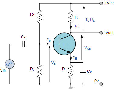
The input signal is from an AC source. The AC signal (${{V}_{s}}$) from this source is superimposed on the bias ${{V}_{BE}}$. ${{V}_{BE}}$ is the voltage of the emitter base junction. When ${{V}_{s}}$ is superimposed on ${{V}_{BE}}$, ${{V}_{BE}}$ changes by an amount $\Delta {{V}_{BE}}$. And this will be equal to the voltage of the input signal. Therefore, $\Delta {{V}_{BE}}={{V}_{s}}$ ….. (i).
The output signal (amplified signal) is received between the collector and the ground (as shown).
Consider ${{V}_{s}}$ = 0.
Then by applying Kirchhoff’s loop law on the output loop we get,
${{V}_{C}}={{V}_{CE}}+{{I}_{C}}{{R}_{C}}$
Similarly, ${{V}_{BE}}={{V}_{B}}$ ……. (ii).
If ${{V}_{s}}\ne 0$, then ${{V}_{s}}+{{V}_{B}}$ will be equal to $\Delta {{V}_{BE}}+{{V}_{BE}}$, from equations (i) and (ii).
When there is change in ${{V}_{BE}}$ there will be a change in current that is flowing in the input resistance ${{r}_{i}}$ . Let the change in current be $\Delta {{I}_{B}}$.
Therefore, we can get,
${{V}_{s}}=\Delta {{V}_{BE}}={{r}_{i}}\Delta {{I}_{B}}$
Due to the change in current ${{I}_{B}}$, there in as change in ${{I}_{C}}$ and therefore the value of ${{V}_{CE}}$ changes. Since ${{V}_{C}}$ is fixed, only the voltage drop across the resistor ${{R}_{L}}$ will change.
Therefore,
$\Delta {{V}_{C}}=\Delta {{V}_{CE}}+{{R}_{L}}\Delta {{I}_{C}}=0$
$\Delta {{V}_{CE}}=-{{R}_{L}}\Delta {{I}_{C}}$
Here, $\Delta {{V}_{C}}={{V}_{o}}$.
${{V}_{o}}=\Delta {{V}_{CE}}=-{{R}_{L}}\Delta {{I}_{C}}$.
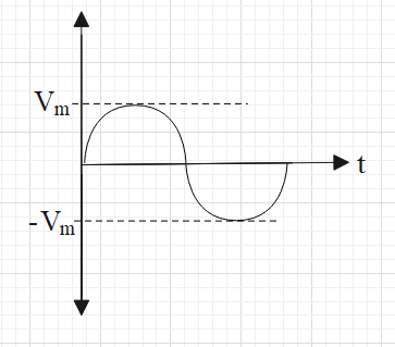
Note: Note that the output signal will be of higher amplitude than the amplitude of input signal but there will be a phase difference of pi between the two signals. Suppose the graph of input signal versus time is as follows:
Then the graph of output signal versus time will be
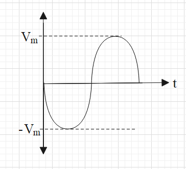
Here, you can see that the maximum voltage of the input source is being amplified. However, the phase of the amplified voltage is changed by one half cycle (i.e. angle of $\pi$).
Formula used:
V=iR
Complete step-by-step answer:
An amplifier is a device that increases the amplitude of the input signal.
A transistor can act as an amplifier, the emitter base junction must be forward biased (FB) and the base collector must be reverse biased (RB) as shown in the figure. The load is connected between the collector and the emitter through DC supply.
The input signal is from an AC source. The AC signal (${{V}_{s}}$) from this source is superimposed on the bias ${{V}_{BE}}$. ${{V}_{BE}}$ is the voltage of the emitter base junction. When ${{V}_{s}}$ is superimposed on ${{V}_{BE}}$, ${{V}_{BE}}$ changes by an amount $\Delta {{V}_{BE}}$. And this will be equal to the voltage of the input signal. Therefore, $\Delta {{V}_{BE}}={{V}_{s}}$ ….. (i).
The output signal (amplified signal) is received between the collector and the ground (as shown).
Consider ${{V}_{s}}$ = 0.
Then by applying Kirchhoff’s loop law on the output loop we get,
${{V}_{C}}={{V}_{CE}}+{{I}_{C}}{{R}_{C}}$
Similarly, ${{V}_{BE}}={{V}_{B}}$ ……. (ii).
If ${{V}_{s}}\ne 0$, then ${{V}_{s}}+{{V}_{B}}$ will be equal to $\Delta {{V}_{BE}}+{{V}_{BE}}$, from equations (i) and (ii).
When there is change in ${{V}_{BE}}$ there will be a change in current that is flowing in the input resistance ${{r}_{i}}$ . Let the change in current be $\Delta {{I}_{B}}$.
Therefore, we can get,
${{V}_{s}}=\Delta {{V}_{BE}}={{r}_{i}}\Delta {{I}_{B}}$
Due to the change in current ${{I}_{B}}$, there in as change in ${{I}_{C}}$ and therefore the value of ${{V}_{CE}}$ changes. Since ${{V}_{C}}$ is fixed, only the voltage drop across the resistor ${{R}_{L}}$ will change.
Therefore,
$\Delta {{V}_{C}}=\Delta {{V}_{CE}}+{{R}_{L}}\Delta {{I}_{C}}=0$
$\Delta {{V}_{CE}}=-{{R}_{L}}\Delta {{I}_{C}}$
Here, $\Delta {{V}_{C}}={{V}_{o}}$.
${{V}_{o}}=\Delta {{V}_{CE}}=-{{R}_{L}}\Delta {{I}_{C}}$.
Note: Note that the output signal will be of higher amplitude than the amplitude of input signal but there will be a phase difference of pi between the two signals. Suppose the graph of input signal versus time is as follows:
Then the graph of output signal versus time will be
Here, you can see that the maximum voltage of the input source is being amplified. However, the phase of the amplified voltage is changed by one half cycle (i.e. angle of $\pi$).
Recently Updated Pages
Master Class 12 Economics: Engaging Questions & Answers for Success
Master Class 12 Physics: Engaging Questions & Answers for Success
Master Class 12 English: Engaging Questions & Answers for Success
Master Class 12 Social Science: Engaging Questions & Answers for Success
Master Class 12 Maths: Engaging Questions & Answers for Success
Master Class 12 Business Studies: Engaging Questions & Answers for Success
Trending doubts
Which are the Top 10 Largest Countries of the World?
What are the major means of transport Explain each class 12 social science CBSE
Draw a labelled sketch of the human eye class 12 physics CBSE
Why cannot DNA pass through cell membranes class 12 biology CBSE
Differentiate between insitu conservation and exsitu class 12 biology CBSE
Draw a neat and well labeled diagram of TS of ovary class 12 biology CBSE