


Draw a closed circuit diagram consisting of $0.5m$ long resistor XY, an ammeter, a voltmeter, four cells of $1.5V$ and a plug key.
Answer
575.7k+ views
Hint: In this question, we need to sketch the circuit diagram which should include $0.5m$ long resistor XY, an ammeter, a voltmeter, four cells of $1.5V$ and a plug key. For this, we will use the concept of the internal as well as the external circuit resistance along with the placement of the different meters in the circuit.
Complete step by step solution:
A circuit diagram is a diagram that shows how different components in a circuit are connected. This is done by using the electrical symbols for the components.
Now, let us draw the required circuit diagram by adding components one by one.
Firstly, we need to draw a $0.5m$ long resistor.
Now, Let us draw an ammeter and a voltmeter.
Let us draw four cells of$1.5V$.
At last, we need a plug key, that is, a switch in our circuit.
Following figure is our expected output.
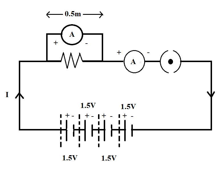
In the figure above,
Battery is of $6V$, that is, it is a combination of four cells each of $1.5V$.
The voltmeter is always connected in parallel.
On the contrary, the ammeter is always connected in series.
A dot with the plug key specifies that the switch is on.
Additional Information:
Cell or battery, connecting wires, ammeter, voltmeter, bulb, etc. are various components on an electric circuit.
The direction of the current is from the positive end to the negative end.
The longer end of the ammeter is the positive end. Similarly, the shorter end of the battery is the negative end.
The positive end of the voltmeter is connected to the positive end of the battery and the negative end of the voltmeter is connected to the negative end of the batter.
Similarly, the positive end of the ammeter is connected to the positive end of the battery and the negative end of the ammeter is connected to the negative end of the batter.
Note:
In a circuit, the voltmeter is always connected in parallel. On the other hand, the ammeter is always connected in series. Students must draw symbols one by one as many students tend to forget drawing one or more components.
Complete step by step solution:
A circuit diagram is a diagram that shows how different components in a circuit are connected. This is done by using the electrical symbols for the components.
Now, let us draw the required circuit diagram by adding components one by one.
Firstly, we need to draw a $0.5m$ long resistor.
Now, Let us draw an ammeter and a voltmeter.
Let us draw four cells of$1.5V$.
At last, we need a plug key, that is, a switch in our circuit.
Following figure is our expected output.
In the figure above,
Battery is of $6V$, that is, it is a combination of four cells each of $1.5V$.
The voltmeter is always connected in parallel.
On the contrary, the ammeter is always connected in series.
A dot with the plug key specifies that the switch is on.
Additional Information:
Cell or battery, connecting wires, ammeter, voltmeter, bulb, etc. are various components on an electric circuit.
The direction of the current is from the positive end to the negative end.
The longer end of the ammeter is the positive end. Similarly, the shorter end of the battery is the negative end.
The positive end of the voltmeter is connected to the positive end of the battery and the negative end of the voltmeter is connected to the negative end of the batter.
Similarly, the positive end of the ammeter is connected to the positive end of the battery and the negative end of the ammeter is connected to the negative end of the batter.
Note:
In a circuit, the voltmeter is always connected in parallel. On the other hand, the ammeter is always connected in series. Students must draw symbols one by one as many students tend to forget drawing one or more components.
Recently Updated Pages
Master Class 12 Economics: Engaging Questions & Answers for Success
Master Class 12 Physics: Engaging Questions & Answers for Success
Master Class 12 English: Engaging Questions & Answers for Success
Master Class 12 Social Science: Engaging Questions & Answers for Success
Master Class 12 Maths: Engaging Questions & Answers for Success
Master Class 12 Business Studies: Engaging Questions & Answers for Success
Trending doubts
Which are the Top 10 Largest Countries of the World?
What are the major means of transport Explain each class 12 social science CBSE
Draw a labelled sketch of the human eye class 12 physics CBSE
Why cannot DNA pass through cell membranes class 12 biology CBSE
Differentiate between insitu conservation and exsitu class 12 biology CBSE
Draw a neat and well labeled diagram of TS of ovary class 12 biology CBSE