


Draw phasor diagram for a series LCR circuit with alternating voltage source, determine the expression for the impedance of the circuit.
Answer
600.3k+ views
Hint: For getting the phasor diagram for the given conditions we will first apply the kvl across the circuit and then from the equations obtained from the kvl we will also get the expressions for the series impedance.
Complete step-by-step answer:
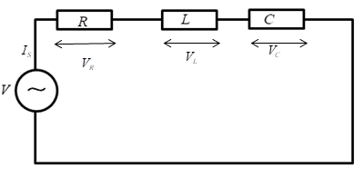
The voltage across each element in the circuit is given by
Let ${I_s} = {I_0}\sin \left( {\omega t} \right)$
Applying KVL in the above circuit
$V = {V_R} + {V_L} + {V_C}..................\left( 1 \right)$
Where
${V_R}$ is the voltage across the resistor
${V_L}$ is the voltage across inductor
${V_C}$ is the voltage across capacitor
Now according to Ohm’s law
V = IR
Now
The voltage across resistor
${V_R} = {I_s}R$
The voltage across inductor
${V_L} = {I_s}{X_L}$
${X_L}$ is the reactance of inductor
The voltage across capacitor
${V_c} = {I_s}{X_C}$
${X_C}$ is the reactance of the capacitor
Substituting these values in the equation (1)
$V = {I_s}R + {I_s}{X_L} + {I_s}{X_C}$
As we know the current leads the voltage by 90 degree in capacitor and lags by 90 degree in case of inductor.
So, taking the magnitude of above equation and assume ${X_L} > {X_C}$
$
V = \sqrt {{{\left( {{I_s}R} \right)}^2} + {{\left( {{I_s}{X_L} - {I_s}{X_C}} \right)}^2}} \\
V = {I_s}\sqrt {{R^2} + {{\left( {{X_L} - {X_C}} \right)}^2}} \\
\dfrac{V}{{{I_s}}} = \sqrt {{R^2} + {{\left( {{X_L} - {X_C}} \right)}^2}} \\
$
Let $\dfrac{V}{{{I_S}}} = Z$
$Z = \sqrt {{R^2} + {{\left( {{X_L} - {X_C}} \right)}^2}} $
Z is known as impedance.
The phasor diagram of the given circuit is shown below.
The resultant vector will be obtained by adding the two vectors ${V_L}$ and ${V_C}$
Because the two vectors are 180 degree apart as shown in the below figure
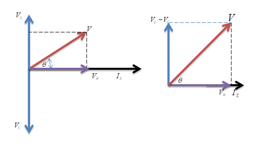
Note – While drawing the phasor diagram, the final reactive voltage must be positive in value therefore take the smallest voltage of the reactive element and subtract it from the largest voltage of the reactive element in the phasor diagram and then take the resultant using the Pythagoras theorem. The current vector is always in phase with the resistance voltage.
Complete step-by-step answer:
The voltage across each element in the circuit is given by
Let ${I_s} = {I_0}\sin \left( {\omega t} \right)$
Applying KVL in the above circuit
$V = {V_R} + {V_L} + {V_C}..................\left( 1 \right)$
Where
${V_R}$ is the voltage across the resistor
${V_L}$ is the voltage across inductor
${V_C}$ is the voltage across capacitor
Now according to Ohm’s law
V = IR
Now
The voltage across resistor
${V_R} = {I_s}R$
The voltage across inductor
${V_L} = {I_s}{X_L}$
${X_L}$ is the reactance of inductor
The voltage across capacitor
${V_c} = {I_s}{X_C}$
${X_C}$ is the reactance of the capacitor
Substituting these values in the equation (1)
$V = {I_s}R + {I_s}{X_L} + {I_s}{X_C}$
As we know the current leads the voltage by 90 degree in capacitor and lags by 90 degree in case of inductor.
So, taking the magnitude of above equation and assume ${X_L} > {X_C}$
$
V = \sqrt {{{\left( {{I_s}R} \right)}^2} + {{\left( {{I_s}{X_L} - {I_s}{X_C}} \right)}^2}} \\
V = {I_s}\sqrt {{R^2} + {{\left( {{X_L} - {X_C}} \right)}^2}} \\
\dfrac{V}{{{I_s}}} = \sqrt {{R^2} + {{\left( {{X_L} - {X_C}} \right)}^2}} \\
$
Let $\dfrac{V}{{{I_S}}} = Z$
$Z = \sqrt {{R^2} + {{\left( {{X_L} - {X_C}} \right)}^2}} $
Z is known as impedance.
The phasor diagram of the given circuit is shown below.
The resultant vector will be obtained by adding the two vectors ${V_L}$ and ${V_C}$
Because the two vectors are 180 degree apart as shown in the below figure
Note – While drawing the phasor diagram, the final reactive voltage must be positive in value therefore take the smallest voltage of the reactive element and subtract it from the largest voltage of the reactive element in the phasor diagram and then take the resultant using the Pythagoras theorem. The current vector is always in phase with the resistance voltage.
Recently Updated Pages
Master Class 12 Economics: Engaging Questions & Answers for Success
Master Class 12 Physics: Engaging Questions & Answers for Success
Master Class 12 English: Engaging Questions & Answers for Success
Master Class 12 Social Science: Engaging Questions & Answers for Success
Master Class 12 Maths: Engaging Questions & Answers for Success
Master Class 12 Business Studies: Engaging Questions & Answers for Success
Trending doubts
Which are the Top 10 Largest Countries of the World?
What are the major means of transport Explain each class 12 social science CBSE
Draw a labelled sketch of the human eye class 12 physics CBSE
Why cannot DNA pass through cell membranes class 12 biology CBSE
Differentiate between insitu conservation and exsitu class 12 biology CBSE
Draw a neat and well labeled diagram of TS of ovary class 12 biology CBSE