


Draw phasor diagram of $ LCR $ series AC circuit.
Answer
538.8k+ views
Hint :In order to solve this question, we are going to first take the circuit for the $ LCR $ series combination. Then, by considering the voltage elements across each and their directions, we can plot the phasor diagrams for the resistance, inductance and the capacitance elements.
Complete Step By Step Answer:
An $ LCR $ series AC circuit is a circuit that consists of a pure resistance of $ R $ ohms, a pure inductance of $ L $ Henry and a pure capacitance $ C $ farads, all connected in series in the circuit. As these elements are connected in series, so the current through each element of the circuit is the same as the total current $ I $ flowing in the circuit.
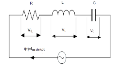
The current relation for this circuit is given by
$ I\left( t \right) = {I_m}\sin \omega t $
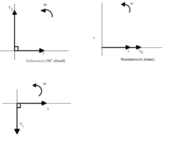
In order to draw the phase diagram, we use the following facts:
(1) The instantaneous voltage across the pure resistance $ R $ , is $ {V_R} $ which is in phase with the applied current.
(2) The instantaneous voltage across the pure inductance $ L $ , is $ {V_L} $ which is $ {90^ \circ } $ ahead of the current.
(3) The instantaneous voltage across the pure inductance $ C $ is $ {V_C} $ which lags the current by $ {90^ \circ } $ .
Thus, the phasor diagram for the circuit can be drawn to depict these voltages as:
Note :
We cannot simply add the voltages $ {V_R} $ , $ {V_L} $ and $ {V_C} $ together to find the support voltage, $ {V_S} $ across all the three components as three voltage vectors point in different directions with regards to the current vector. Therefore, we will have to find the supply voltage as the phasor sum of all the three component voltages together vectorially.
Complete Step By Step Answer:
An $ LCR $ series AC circuit is a circuit that consists of a pure resistance of $ R $ ohms, a pure inductance of $ L $ Henry and a pure capacitance $ C $ farads, all connected in series in the circuit. As these elements are connected in series, so the current through each element of the circuit is the same as the total current $ I $ flowing in the circuit.
The current relation for this circuit is given by
$ I\left( t \right) = {I_m}\sin \omega t $
In order to draw the phase diagram, we use the following facts:
(1) The instantaneous voltage across the pure resistance $ R $ , is $ {V_R} $ which is in phase with the applied current.
(2) The instantaneous voltage across the pure inductance $ L $ , is $ {V_L} $ which is $ {90^ \circ } $ ahead of the current.
(3) The instantaneous voltage across the pure inductance $ C $ is $ {V_C} $ which lags the current by $ {90^ \circ } $ .
Thus, the phasor diagram for the circuit can be drawn to depict these voltages as:
Note :
We cannot simply add the voltages $ {V_R} $ , $ {V_L} $ and $ {V_C} $ together to find the support voltage, $ {V_S} $ across all the three components as three voltage vectors point in different directions with regards to the current vector. Therefore, we will have to find the supply voltage as the phasor sum of all the three component voltages together vectorially.
Recently Updated Pages
Master Class 12 Economics: Engaging Questions & Answers for Success
Master Class 12 Physics: Engaging Questions & Answers for Success
Master Class 12 English: Engaging Questions & Answers for Success
Master Class 12 Social Science: Engaging Questions & Answers for Success
Master Class 12 Maths: Engaging Questions & Answers for Success
Master Class 12 Business Studies: Engaging Questions & Answers for Success
Trending doubts
Which are the Top 10 Largest Countries of the World?
What are the major means of transport Explain each class 12 social science CBSE
Draw a labelled sketch of the human eye class 12 physics CBSE
What is a transformer Explain the principle construction class 12 physics CBSE
Why cannot DNA pass through cell membranes class 12 biology CBSE
Differentiate between insitu conservation and exsitu class 12 biology CBSE