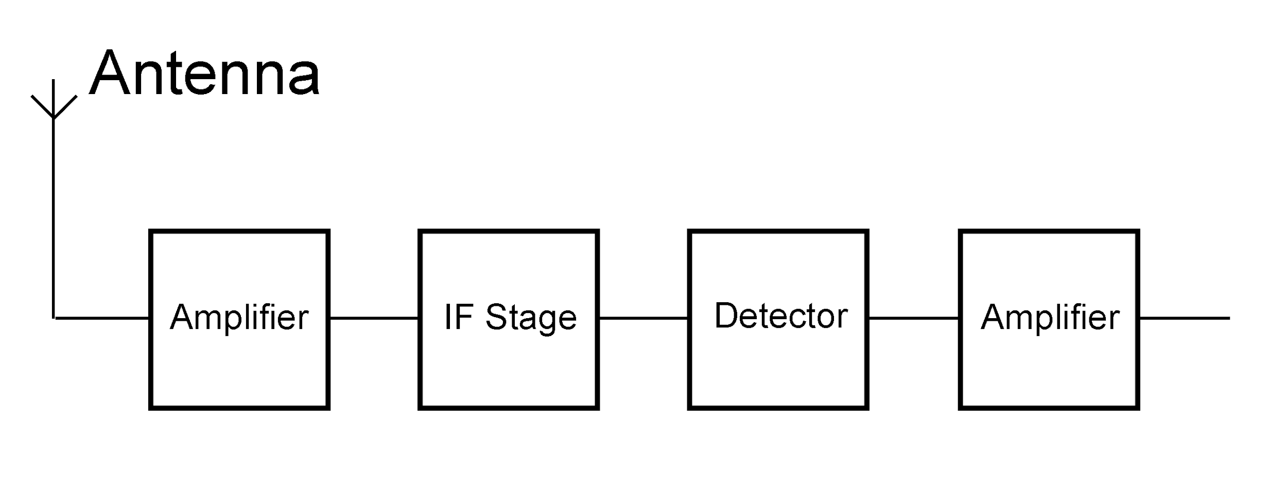
Draw the block diagram of an AM receiver.
Answer
579.6k+ views
Hint: Amplitude modulation receiver is electrical equipment that receives an amplitude modulated wave as input and produces the original signal as an output. Draw a block diagram of the AM receiver including receiving antenna, amplifier, IF stage, detector, and amplifier, and briefly explain them.
Complete answer:
AM receiver – Amplitude modulation receiver is electrical equipment that receives an amplitude modulated wave as input and produces the original signal as an output.
The block diagram of an AM receiver is shown below

The basic description of all the parts of the AM receiver is as follows
Receiving antenna – A receiving antenna functions opposite to a transmission antenna and receives the amplitude-modulated wave and converts it into electric current and feeds it to the amplifier.
Amplifier – An amplifier is a piece of equipment that is used to amplify the signal received by the antenna.
IF stage – In the intermediate-frequency amplifier stage the intermediate frequencies of the amplified signals are filtered and amplified before feeding it the demodulator, this makes the process of demodulation easier.
Detector – It is a device or circuit, used to extract the desired signal from the carrier wave, a process called demodulation
Amplifier- It is a component that amplifies the low power electric signals that have become low after the IF stage and the process of demodulation.
This signal can now be used for the desired device (maybe a TV or a radio).
Note:
A block diagram is essentially a diagram that shows a simple schematic form based on the general arrangement of components in a complex system. Block diagrams like other visual aids, make the process of understanding and explaining complex systems easy and more efficient.
Complete answer:
AM receiver – Amplitude modulation receiver is electrical equipment that receives an amplitude modulated wave as input and produces the original signal as an output.
The block diagram of an AM receiver is shown below

The basic description of all the parts of the AM receiver is as follows
Receiving antenna – A receiving antenna functions opposite to a transmission antenna and receives the amplitude-modulated wave and converts it into electric current and feeds it to the amplifier.
Amplifier – An amplifier is a piece of equipment that is used to amplify the signal received by the antenna.
IF stage – In the intermediate-frequency amplifier stage the intermediate frequencies of the amplified signals are filtered and amplified before feeding it the demodulator, this makes the process of demodulation easier.
Detector – It is a device or circuit, used to extract the desired signal from the carrier wave, a process called demodulation
Amplifier- It is a component that amplifies the low power electric signals that have become low after the IF stage and the process of demodulation.
This signal can now be used for the desired device (maybe a TV or a radio).
Note:
A block diagram is essentially a diagram that shows a simple schematic form based on the general arrangement of components in a complex system. Block diagrams like other visual aids, make the process of understanding and explaining complex systems easy and more efficient.
Recently Updated Pages
Master Class 12 Economics: Engaging Questions & Answers for Success

Master Class 12 Physics: Engaging Questions & Answers for Success

Master Class 12 English: Engaging Questions & Answers for Success

Master Class 12 Social Science: Engaging Questions & Answers for Success

Master Class 12 Maths: Engaging Questions & Answers for Success

Master Class 12 Business Studies: Engaging Questions & Answers for Success

Trending doubts
Which are the Top 10 Largest Countries of the World?

What are the major means of transport Explain each class 12 social science CBSE

Draw a labelled sketch of the human eye class 12 physics CBSE

Why cannot DNA pass through cell membranes class 12 biology CBSE

Differentiate between insitu conservation and exsitu class 12 biology CBSE

Draw a neat and well labeled diagram of TS of ovary class 12 biology CBSE


