


Draw the circuit diagram of the voltage regulator using the Zener diode.
Answer
585.9k+ views
Hint: Zener diode is a type of a diode which is doped properly to give the sharp breakdown voltage. It can be used as a voltage regulator to maintain a constant voltage for the varying voltage provided by the source to the circuit. Here we will draw the circuit for the Zener diode when used as a voltage regulator.
Complete step-by-step solution:
A Zener diode is a diode, which works in a breakdown region and it is used in the reversed biased condition. Let us draw a reverse characteristic of the Zener diode for a better understanding.
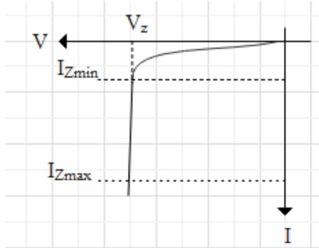
As we can see that for the range \[{{I}_{\text{Zmin}}}\text{ to }{{I}_{\text{Zmax}}}\] zener voltage is approximately constant and this region for which zener voltage is constant is the breakdown region. \[{{I}_{\text{Zmin}}}\] is also called knee voltage or we can say it is the minimum value of zener current whereas \[{{I}_{\text{Zmax}}}\] is the maximum value of zener current beyond this value the zener diode will burst. Therefore zener diode is used within the range of \[{{I}_{\text{Zmin}}}\text{ to }{{I}_{\text{Zmax}}}\].
Now, as Zener voltage remains the same for the range \[{{I}_{\text{Zmin}}}\text{ to }{{I}_{\text{Zmax}}}\] it can be used as a voltage regulator when it is operated in the breakdown region. Because the work of a voltage regulator is to keep the output voltage the same for varying input. To understand how Zener diode works as a voltage regulator let us draw a circuit diagram for the voltage regulator using Zener diode.
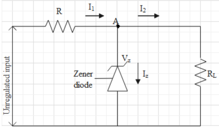
Here we can see from the diagram, there are two resistors R and \[{{R}_{L}}\] where R is connected in series so as to absorb all the fluctuation of the output voltage and \[{{R}_{L}}\] is the load resistance across which output voltage is obtained. \[{{V}_{Z}}\] is the Zener voltage and \[{{I}_{1}}\] is the current flowing through the circuit which divides into \[{{I}_{Z}}\] and \[{{I}_{2}}\]. \[{{I}_{Z}}\] is the Zener current flowing through the Zener diode and I2 is the current flowing through load RL.
Now if we apply Kirchhoff’s current law at node A we can write
\[{{I}_{1}}={{I}_{Z}}+{{I}_{2}}\]
Now there can be two cases when the source is varying or input is varying and when the load resistance is varying. Let’s take the first case where input is varying, in this case, the extra voltage or the fluctuation is absorbed by series resistance R due to which total current or \[{{I}_{1}}\] will increase but this increase is balanced by Zener current \[{{I}_{Z}}\] and so \[{{I}_{2}}\] doesn’t change resulting constant output voltage across load resistance.
In the second case that is when load resistance changes and input is fixed then there should be an increase in load current\[{{I}_{2}}\]. As input is constant \[{{I}_{1}}\] remains the same and the change is compensated by Zener current \[{{I}_{Z}}\]. For example, if load resistance decreases then load current should increase so that output remains the same, therefore Zener current decreases so as to provide the amount of current required at load resistance to keep the voltage constant ( because total current \[{{I}_{1}}\] remains constant).
Hence this way Zener diodes can be used as a voltage regulator.
Note: Zener diode is always reversed biased and the breakdown voltage or the Zener voltage depends on the doping of the diode. If the diode is lightly doped then the depletion layer will be thin and so we get a lower breakdown voltage. If the diode is heavily doped then the depletion region will be greater resulting in higher breakdown voltage. For voltage stabilizer, a heavily doped diode should be used, so as to get constant voltage over a large range of varying input voltage. Note that when the source voltage or input voltage is less than Zener voltage Zener diode works as an open circuit.
Complete step-by-step solution:
A Zener diode is a diode, which works in a breakdown region and it is used in the reversed biased condition. Let us draw a reverse characteristic of the Zener diode for a better understanding.
As we can see that for the range \[{{I}_{\text{Zmin}}}\text{ to }{{I}_{\text{Zmax}}}\] zener voltage is approximately constant and this region for which zener voltage is constant is the breakdown region. \[{{I}_{\text{Zmin}}}\] is also called knee voltage or we can say it is the minimum value of zener current whereas \[{{I}_{\text{Zmax}}}\] is the maximum value of zener current beyond this value the zener diode will burst. Therefore zener diode is used within the range of \[{{I}_{\text{Zmin}}}\text{ to }{{I}_{\text{Zmax}}}\].
Now, as Zener voltage remains the same for the range \[{{I}_{\text{Zmin}}}\text{ to }{{I}_{\text{Zmax}}}\] it can be used as a voltage regulator when it is operated in the breakdown region. Because the work of a voltage regulator is to keep the output voltage the same for varying input. To understand how Zener diode works as a voltage regulator let us draw a circuit diagram for the voltage regulator using Zener diode.
Here we can see from the diagram, there are two resistors R and \[{{R}_{L}}\] where R is connected in series so as to absorb all the fluctuation of the output voltage and \[{{R}_{L}}\] is the load resistance across which output voltage is obtained. \[{{V}_{Z}}\] is the Zener voltage and \[{{I}_{1}}\] is the current flowing through the circuit which divides into \[{{I}_{Z}}\] and \[{{I}_{2}}\]. \[{{I}_{Z}}\] is the Zener current flowing through the Zener diode and I2 is the current flowing through load RL.
Now if we apply Kirchhoff’s current law at node A we can write
\[{{I}_{1}}={{I}_{Z}}+{{I}_{2}}\]
Now there can be two cases when the source is varying or input is varying and when the load resistance is varying. Let’s take the first case where input is varying, in this case, the extra voltage or the fluctuation is absorbed by series resistance R due to which total current or \[{{I}_{1}}\] will increase but this increase is balanced by Zener current \[{{I}_{Z}}\] and so \[{{I}_{2}}\] doesn’t change resulting constant output voltage across load resistance.
In the second case that is when load resistance changes and input is fixed then there should be an increase in load current\[{{I}_{2}}\]. As input is constant \[{{I}_{1}}\] remains the same and the change is compensated by Zener current \[{{I}_{Z}}\]. For example, if load resistance decreases then load current should increase so that output remains the same, therefore Zener current decreases so as to provide the amount of current required at load resistance to keep the voltage constant ( because total current \[{{I}_{1}}\] remains constant).
Hence this way Zener diodes can be used as a voltage regulator.
Note: Zener diode is always reversed biased and the breakdown voltage or the Zener voltage depends on the doping of the diode. If the diode is lightly doped then the depletion layer will be thin and so we get a lower breakdown voltage. If the diode is heavily doped then the depletion region will be greater resulting in higher breakdown voltage. For voltage stabilizer, a heavily doped diode should be used, so as to get constant voltage over a large range of varying input voltage. Note that when the source voltage or input voltage is less than Zener voltage Zener diode works as an open circuit.
Recently Updated Pages
Master Class 12 Economics: Engaging Questions & Answers for Success
Master Class 12 Physics: Engaging Questions & Answers for Success
Master Class 12 English: Engaging Questions & Answers for Success
Master Class 12 Social Science: Engaging Questions & Answers for Success
Master Class 12 Maths: Engaging Questions & Answers for Success
Master Class 12 Business Studies: Engaging Questions & Answers for Success
Trending doubts
Which are the Top 10 Largest Countries of the World?
What are the major means of transport Explain each class 12 social science CBSE
Draw a labelled sketch of the human eye class 12 physics CBSE
Why cannot DNA pass through cell membranes class 12 biology CBSE
Differentiate between insitu conservation and exsitu class 12 biology CBSE
Draw a neat and well labeled diagram of TS of ovary class 12 biology CBSE