Draw the circuit of a full wave rectifier using two p-n junction diodes and explain its working. Show the input and output waveforms?
Answer
591.6k+ views
Hint: An electrical device that converts A.C input signal into D.C output signal is known as a rectifier. The direct current flows only in one direction.
Complete step by step answer:
A full-wave rectifier converts the whole of the input waveform to one of constant polarity (either positive or negative) at its output. Mathematically, this corresponds to the absolute value function. In a half wave rectifier there are two diodes and a center tapped transformer, or four diodes in a bridge configuration and any AC source.
Characteristics of full wave rectifier:
Ripple factor:
The ratio of the root mean square value of A.C output voltage to the D.C input voltage is known as the Ripple factor.
\[Ripplefactor = \sqrt {{{\left( {\dfrac{{{V_{rms}}}}{{{V_{DC}}}}} \right)}^2}} - 1\]
Where,
\[{V_{rms}}\] is the voltage of the root mean square.
\[{V_{DC}}\]is the D.C voltage.
D.C current:
${I_{D.C}} = \dfrac{{2{I_{\max }}}}{\pi }$
Where,
${I_{D.C}}$ is the D.C current
D.C output voltage:
Output voltage is obtained at the load resistor ${R_l}$. It is given as:
${V_{D.C}} = \dfrac{{2{V_{\max }}}}{\pi }$
Where ${V_{D.C}}$is the D.C Voltage.
Efficiency of a full wave rectifier is $81.2\% $.
Types of full wave rectifier:
Two diodes full wave rectifier
Bridge rectifier
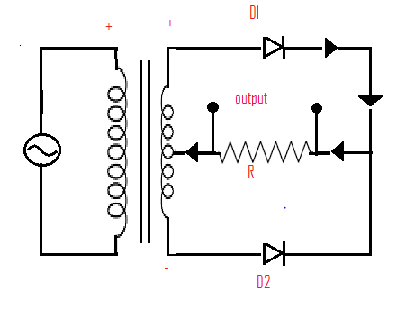
Following is the circuit diagram of a full wave rectifier.

From the diagram, it is given that,
D1, D2 are two diodes
Rl is the load resistor
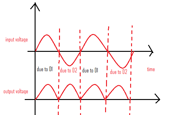
Working of a full wave rectifier: during the first half of the input cycle, the upper end of the coil is at positive potential and lower end at negative potential. The forward biased is Diode 1 and reversed biased id Diode 2. The current flows in output load as shown in the figure. During the second half D1 is reverse biased and D2 is forward biased. Current will flow in the lower circuit. This way the current flows in one direction.
Following is the output wave form of full wave rectifier.

Advantages:
Full wave rectifier has more efficiency compared to the half-wave rectifier.
The power loss is very low.
The ripples generated are less.
Disadvantages:
Very expensive.
Note:
When only one part of the A.C input signal is rectified it is known as Half- wave rectifier.
The half wave rectifiers have both positive and negative wave cycles. During the positive half of the input the current flows from positive to negative making the forward biased. During the negative half cycle the input current flows from negative to positive making the diode reversed biased.
The rectifier efficiency for the half wave is $40.6\% $.
Complete step by step answer:
A full-wave rectifier converts the whole of the input waveform to one of constant polarity (either positive or negative) at its output. Mathematically, this corresponds to the absolute value function. In a half wave rectifier there are two diodes and a center tapped transformer, or four diodes in a bridge configuration and any AC source.
Characteristics of full wave rectifier:
Ripple factor:
The ratio of the root mean square value of A.C output voltage to the D.C input voltage is known as the Ripple factor.
\[Ripplefactor = \sqrt {{{\left( {\dfrac{{{V_{rms}}}}{{{V_{DC}}}}} \right)}^2}} - 1\]
Where,
\[{V_{rms}}\] is the voltage of the root mean square.
\[{V_{DC}}\]is the D.C voltage.
D.C current:
${I_{D.C}} = \dfrac{{2{I_{\max }}}}{\pi }$
Where,
${I_{D.C}}$ is the D.C current
D.C output voltage:
Output voltage is obtained at the load resistor ${R_l}$. It is given as:
${V_{D.C}} = \dfrac{{2{V_{\max }}}}{\pi }$
Where ${V_{D.C}}$is the D.C Voltage.
Efficiency of a full wave rectifier is $81.2\% $.
Types of full wave rectifier:
Two diodes full wave rectifier
Bridge rectifier
Following is the circuit diagram of a full wave rectifier.

From the diagram, it is given that,
D1, D2 are two diodes
Rl is the load resistor
Working of a full wave rectifier: during the first half of the input cycle, the upper end of the coil is at positive potential and lower end at negative potential. The forward biased is Diode 1 and reversed biased id Diode 2. The current flows in output load as shown in the figure. During the second half D1 is reverse biased and D2 is forward biased. Current will flow in the lower circuit. This way the current flows in one direction.
Following is the output wave form of full wave rectifier.

Advantages:
Full wave rectifier has more efficiency compared to the half-wave rectifier.
The power loss is very low.
The ripples generated are less.
Disadvantages:
Very expensive.
Note:
When only one part of the A.C input signal is rectified it is known as Half- wave rectifier.
The half wave rectifiers have both positive and negative wave cycles. During the positive half of the input the current flows from positive to negative making the forward biased. During the negative half cycle the input current flows from negative to positive making the diode reversed biased.
The rectifier efficiency for the half wave is $40.6\% $.
Recently Updated Pages
Master Class 12 Economics: Engaging Questions & Answers for Success

Master Class 12 Physics: Engaging Questions & Answers for Success

Master Class 12 English: Engaging Questions & Answers for Success

Master Class 12 Social Science: Engaging Questions & Answers for Success

Master Class 12 Maths: Engaging Questions & Answers for Success

Master Class 12 Business Studies: Engaging Questions & Answers for Success

Trending doubts
Which are the Top 10 Largest Countries of the World?

What are the major means of transport Explain each class 12 social science CBSE

Draw a labelled sketch of the human eye class 12 physics CBSE

Why cannot DNA pass through cell membranes class 12 biology CBSE

Differentiate between insitu conservation and exsitu class 12 biology CBSE

Draw a neat and well labeled diagram of TS of ovary class 12 biology CBSE


