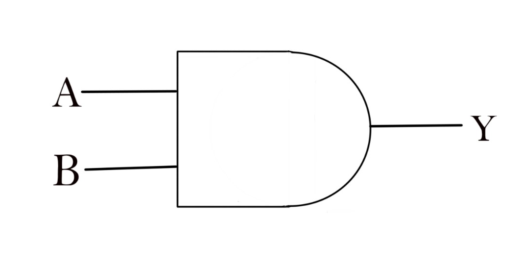
Draw the logic symbol of AND gate.
Answer
585.3k+ views
Hint: The AND gate with inputs A and B and output C implements the logical expression $Y = A.B$
This means that the output is the product of inputs. The symbol of AND the gate is like the shape of the fourth letter of the English alphabet “D”.
Complete step by step answer:
Logic AND gate:

The input at end A and end B can be 0 or 1. All the permutations of inputs shown in the table are known as a truth table. The truth table for the AND gate is given below.
Additional information:
A logic gate is an elementary building block of a digital circuit. Most logic gates have two inputs and one output. At any given moment, every terminal is in one of the two binary conditions low (0) or high (1), represented by a different voltage.
These are usually used in binary systems and it is possible to create any required logic with these three gates. In practice when used in complex logic systems with multiple inputs and outputs the propagation delays of the gate must be taken into account and the output read a certain time after the inputs are set.
Note:
The basic logic gates are AND, OR, and NOT. It's the basic combination of transistors that can "make sense" or implement logic.
Logic gates are used in most of the digital components, ICs, devices, circuits, and devices.
The basic fundamental component of any processor, microprocessor, and microcontroller is the logic gate. ALU, Registers, memories in a processor are made of logic gates.
This means that the output is the product of inputs. The symbol of AND the gate is like the shape of the fourth letter of the English alphabet “D”.
Complete step by step answer:
Logic AND gate:

The input at end A and end B can be 0 or 1. All the permutations of inputs shown in the table are known as a truth table. The truth table for the AND gate is given below.
| A | B | Y |
| 0 | 0 | 0 |
| 0 | 1 | 0 |
| 1 | 0 | 0 |
| 1 | 1 | 1 |
Additional information:
A logic gate is an elementary building block of a digital circuit. Most logic gates have two inputs and one output. At any given moment, every terminal is in one of the two binary conditions low (0) or high (1), represented by a different voltage.
These are usually used in binary systems and it is possible to create any required logic with these three gates. In practice when used in complex logic systems with multiple inputs and outputs the propagation delays of the gate must be taken into account and the output read a certain time after the inputs are set.
Note:
The basic logic gates are AND, OR, and NOT. It's the basic combination of transistors that can "make sense" or implement logic.
Logic gates are used in most of the digital components, ICs, devices, circuits, and devices.
The basic fundamental component of any processor, microprocessor, and microcontroller is the logic gate. ALU, Registers, memories in a processor are made of logic gates.
Recently Updated Pages
Master Class 12 Economics: Engaging Questions & Answers for Success

Master Class 12 Physics: Engaging Questions & Answers for Success

Master Class 12 English: Engaging Questions & Answers for Success

Master Class 12 Social Science: Engaging Questions & Answers for Success

Master Class 12 Maths: Engaging Questions & Answers for Success

Master Class 12 Business Studies: Engaging Questions & Answers for Success

Trending doubts
Which are the Top 10 Largest Countries of the World?

What are the major means of transport Explain each class 12 social science CBSE

Draw a labelled sketch of the human eye class 12 physics CBSE

Why cannot DNA pass through cell membranes class 12 biology CBSE

Differentiate between insitu conservation and exsitu class 12 biology CBSE

Draw a neat and well labeled diagram of TS of ovary class 12 biology CBSE


