Explain the use of \[P - N\] junction diode as full wave rectifier on the basis of the following points.
(i)Labelled circuit diagram
(ii)Working method
(iii)Graph between input and output potential with variation of the time
Answer
584.1k+ views
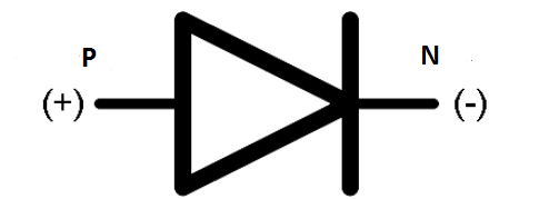
Hint: This problem can be solved by drawing a proper diagram and having knowledge about the \[P - N\] junction diode and application of it. Diode is a device which has two terminals. It’s used to control the flow of current. Diode is a device which is made by \[P - \] type semiconductor and \[N - \] type of semiconductor which connect through high pressure and temperature.This device has two terminals so it’s called diode.
Formula used:
Diode is a device which is made by \[P - \] type semiconductor and \[N - \] type of semiconductor which connect through high pressure and temperature.
This device has two terminals so it’s called a diode.
In \[P - N\] junction diode can be biased by two way
Forward biasing :- \[P - \] terminal of diode connected to the positive terminal and \[N - \] terminal connected to the negative terminal of battery or cell is called forward biasing.
In this diode work as simple connecting wire
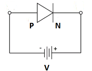
Reverse biasing:- \[P - \] terminal of diode connected to the negative terminal and \[N - \] terminal connected to the positive terminal of battery or cell is called reverse biasing.
This diode works as a cut-off.
\[P - N\] junction diode one of the applications is a rectifier.
Rectifier is device which converts alternate current in to direct current
Complete step by step answer:
Diode is a device which is made by \[P - \] type semiconductor and \[N - \] type of semiconductor which connect through high pressure and temperature.
This device has two terminals so it’s called a diode.

In \[P - N\] junction diode can be biased by two way
1) Forward biasing :- \[P - \] terminal of diode connected to the positive terminal and \[N - \] terminal connected to the negative terminal of battery or cell is called forward biasing. This diode works as a simple connecting wire.

2) Reverse biasing:- \[P - \] terminal of diode connected to the negative terminal and \[N - \] terminal connected to the positive terminal of battery or cell is called reverse biasing.In this diode works as a cut-off.

\[P - N\] junction diode one of the applications is a rectifier.
Rectifier is a device which converts alternating current into direct current.


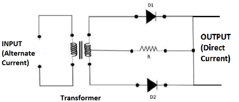
In the full wave rectifier used
Alternate current as input.
Transformer to control the voltage.
Resistance for the balancing output current.
Two diodes used parallel to each other.
A transformer is a normal transformer that has a slight modification in it. Its secondary winding has a wire connected at the diode. Hence the input supply AC voltage while passing through the secondary winding its voltage is divided into two halves. The one half is referred to as the positive half of the voltage. Whereas the remaining half of the voltage is for the negative part of the cycle.
Working theory: The circuit consists of two diodes that are connected in parallel to each other along with the resistive load. The load is connected at the wire of the secondary winding.
The input is provided to the transformer as it reaches the secondary winding the voltage is divided into two halves. During the positive half of the input cycles, the diode \[D{}_1\] is in forwarding bias condition indicating the conducting mode and the diode \[D{}_2\] is in the non-conducting mode because it is in reverse bias condition. The flow of current is observed at the terminal of diode \[D{}_1\] .
During the negative half of the cycle, the diode \[D{}_2\] conducts because of the c transformer property and the diode \[D{}_1\] is in reverse bias condition that is in non-conduction mode. During this consequence the terminal at \[D{}_2\] one can find the flow of current through it and at \[D{}_1\] there is no evident flow of current or the current is blocked at \[D{}_1\] terminal.
During positive cycle diode \[D{}_1\] is in the range of conduction and when the negative cycle is provided the diode \[D{}_2\] will be in the conducting stage. Hence both the cycles are utilized here for rectification without any loss of input power. Hence we can say that the average output voltage of the full-wave rectifier is doubled compared to that of the half-wave rectifier
Graph between Input voltage respect to the time
Input voltage changes its direction every time of interval. This voltage is called alternate voltage (AV) .

Graph between Output voltage respect to the time
Input voltage does not change its direction every time of interval. This voltage is called direct voltage (DV) .

Note:
This problem can be solved by drawing a proper diagram and having knowledge about the \[P - N\] junction diode and application of it. You should know about the position of diodes in the circuit. You should know about the alternate current and voltage as well as direct current and direct voltage.
Formula used:
Diode is a device which is made by \[P - \] type semiconductor and \[N - \] type of semiconductor which connect through high pressure and temperature.
This device has two terminals so it’s called a diode.
In \[P - N\] junction diode can be biased by two way
Forward biasing :- \[P - \] terminal of diode connected to the positive terminal and \[N - \] terminal connected to the negative terminal of battery or cell is called forward biasing.
In this diode work as simple connecting wire
Reverse biasing:- \[P - \] terminal of diode connected to the negative terminal and \[N - \] terminal connected to the positive terminal of battery or cell is called reverse biasing.
This diode works as a cut-off.
\[P - N\] junction diode one of the applications is a rectifier.
Rectifier is device which converts alternate current in to direct current
Complete step by step answer:
Diode is a device which is made by \[P - \] type semiconductor and \[N - \] type of semiconductor which connect through high pressure and temperature.
This device has two terminals so it’s called a diode.

In \[P - N\] junction diode can be biased by two way
1) Forward biasing :- \[P - \] terminal of diode connected to the positive terminal and \[N - \] terminal connected to the negative terminal of battery or cell is called forward biasing. This diode works as a simple connecting wire.

2) Reverse biasing:- \[P - \] terminal of diode connected to the negative terminal and \[N - \] terminal connected to the positive terminal of battery or cell is called reverse biasing.In this diode works as a cut-off.

\[P - N\] junction diode one of the applications is a rectifier.
Rectifier is a device which converts alternating current into direct current.


In the full wave rectifier used
Alternate current as input.
Transformer to control the voltage.
Resistance for the balancing output current.
Two diodes used parallel to each other.
A transformer is a normal transformer that has a slight modification in it. Its secondary winding has a wire connected at the diode. Hence the input supply AC voltage while passing through the secondary winding its voltage is divided into two halves. The one half is referred to as the positive half of the voltage. Whereas the remaining half of the voltage is for the negative part of the cycle.
Working theory: The circuit consists of two diodes that are connected in parallel to each other along with the resistive load. The load is connected at the wire of the secondary winding.
The input is provided to the transformer as it reaches the secondary winding the voltage is divided into two halves. During the positive half of the input cycles, the diode \[D{}_1\] is in forwarding bias condition indicating the conducting mode and the diode \[D{}_2\] is in the non-conducting mode because it is in reverse bias condition. The flow of current is observed at the terminal of diode \[D{}_1\] .
During the negative half of the cycle, the diode \[D{}_2\] conducts because of the c transformer property and the diode \[D{}_1\] is in reverse bias condition that is in non-conduction mode. During this consequence the terminal at \[D{}_2\] one can find the flow of current through it and at \[D{}_1\] there is no evident flow of current or the current is blocked at \[D{}_1\] terminal.
During positive cycle diode \[D{}_1\] is in the range of conduction and when the negative cycle is provided the diode \[D{}_2\] will be in the conducting stage. Hence both the cycles are utilized here for rectification without any loss of input power. Hence we can say that the average output voltage of the full-wave rectifier is doubled compared to that of the half-wave rectifier
Graph between Input voltage respect to the time
Input voltage changes its direction every time of interval. This voltage is called alternate voltage (AV) .

Graph between Output voltage respect to the time
Input voltage does not change its direction every time of interval. This voltage is called direct voltage (DV) .

Note:
This problem can be solved by drawing a proper diagram and having knowledge about the \[P - N\] junction diode and application of it. You should know about the position of diodes in the circuit. You should know about the alternate current and voltage as well as direct current and direct voltage.
Recently Updated Pages
Master Class 12 Economics: Engaging Questions & Answers for Success

Master Class 12 Physics: Engaging Questions & Answers for Success

Master Class 12 English: Engaging Questions & Answers for Success

Master Class 12 Social Science: Engaging Questions & Answers for Success

Master Class 12 Maths: Engaging Questions & Answers for Success

Master Class 12 Business Studies: Engaging Questions & Answers for Success

Trending doubts
Which are the Top 10 Largest Countries of the World?

What are the major means of transport Explain each class 12 social science CBSE

Draw a labelled sketch of the human eye class 12 physics CBSE

Why cannot DNA pass through cell membranes class 12 biology CBSE

Differentiate between insitu conservation and exsitu class 12 biology CBSE

Draw a neat and well labeled diagram of TS of ovary class 12 biology CBSE


