Explain with a neat diagram, how a p-n junction diode is used as a half wave rectifier.
Answer
568.2k+ views
Hint:First of all, we know that there should be a step-down transformer. The primary coil is supplied with the input AC voltage. The diodes either allow the negative current or positive current to pass through depending on the connection. We will draw the connections accordingly and elaborate the working.
Complete answer:
In the given question, we are given a p-n junction diode which is used as a half wave rectifier.
We are asked to explain the working of the p-n junction diode when made to work as a half wave rectifier.
To begin with, we will discuss a bit about the half wave rectifier circuit. Only one half of the input sine wave (either positive or negative) passes through the half wave rectifier and rejects the other half. Pulsating DC is the output of the half wave rectifier. Using the filtration system, the ripple in the output waveform can be reduced. half-wave rectification eliminates only the negative voltage portion using a single diode.
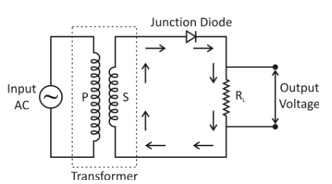
To have a better understanding let us draw a diagram as given below:

Now, we will discuss the working in detail:
The AC feedback signal to be corrected is fed to the transformer 's main (P) coil via a load resistance ${R_L}$, the secondary (S) coil is linked to the junction diode. As the positive half of the AC input signal passes through the primary coil, owing to mutual induction, the induced emf is set up in the secondary coil. The position of induced emf is such that it becomes positive in the upper end of the secondary coil and negative in the lower end. As the upper end of the secondary coil is bound to the p-region of the junction diode, during the positive half of the AC signal, the junction diode is forward biased. Thus, in the direction shown by arrows, the junction diode conducts and current flow begins. The output voltage that varies according to the half-cycle of the input is obtained through ${R_L}$.
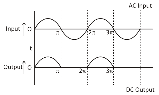
As the negative half-cycle of AC input passes into the primary coil, owing to reciprocal induction, induced emf is again set up around the secondary coil. The direction of induced emf is now such that it becomes negative at the upper end of the secondary coil and positive at the lower end. So, the junction diode is biased in reverse. Thus, the junction diode does not operate, and therefore, during the negative half of input AC, we get no output overload resistance. As shown, the input and corresponding output voltages:

Note:While answering the question, one should remember that the number of turns in the primary circuit is more than the secondary circuit. Hence, we can conclude that the voltage is decreased in the secondary circuit. Most of the students tend to make this mistake while drawing the diagram. The diode is connected in such a way that it allows either positive or negative part to pass through, to generate the DC voltage.
Complete answer:
In the given question, we are given a p-n junction diode which is used as a half wave rectifier.
We are asked to explain the working of the p-n junction diode when made to work as a half wave rectifier.
To begin with, we will discuss a bit about the half wave rectifier circuit. Only one half of the input sine wave (either positive or negative) passes through the half wave rectifier and rejects the other half. Pulsating DC is the output of the half wave rectifier. Using the filtration system, the ripple in the output waveform can be reduced. half-wave rectification eliminates only the negative voltage portion using a single diode.
To have a better understanding let us draw a diagram as given below:

Now, we will discuss the working in detail:
The AC feedback signal to be corrected is fed to the transformer 's main (P) coil via a load resistance ${R_L}$, the secondary (S) coil is linked to the junction diode. As the positive half of the AC input signal passes through the primary coil, owing to mutual induction, the induced emf is set up in the secondary coil. The position of induced emf is such that it becomes positive in the upper end of the secondary coil and negative in the lower end. As the upper end of the secondary coil is bound to the p-region of the junction diode, during the positive half of the AC signal, the junction diode is forward biased. Thus, in the direction shown by arrows, the junction diode conducts and current flow begins. The output voltage that varies according to the half-cycle of the input is obtained through ${R_L}$.
As the negative half-cycle of AC input passes into the primary coil, owing to reciprocal induction, induced emf is again set up around the secondary coil. The direction of induced emf is now such that it becomes negative at the upper end of the secondary coil and positive at the lower end. So, the junction diode is biased in reverse. Thus, the junction diode does not operate, and therefore, during the negative half of input AC, we get no output overload resistance. As shown, the input and corresponding output voltages:

Note:While answering the question, one should remember that the number of turns in the primary circuit is more than the secondary circuit. Hence, we can conclude that the voltage is decreased in the secondary circuit. Most of the students tend to make this mistake while drawing the diagram. The diode is connected in such a way that it allows either positive or negative part to pass through, to generate the DC voltage.
Recently Updated Pages
Master Class 12 Economics: Engaging Questions & Answers for Success

Master Class 12 Physics: Engaging Questions & Answers for Success

Master Class 12 English: Engaging Questions & Answers for Success

Master Class 12 Social Science: Engaging Questions & Answers for Success

Master Class 12 Maths: Engaging Questions & Answers for Success

Master Class 12 Business Studies: Engaging Questions & Answers for Success

Trending doubts
Which are the Top 10 Largest Countries of the World?

What are the major means of transport Explain each class 12 social science CBSE

Draw a labelled sketch of the human eye class 12 physics CBSE

Why cannot DNA pass through cell membranes class 12 biology CBSE

Differentiate between insitu conservation and exsitu class 12 biology CBSE

Draw a neat and well labeled diagram of TS of ovary class 12 biology CBSE


