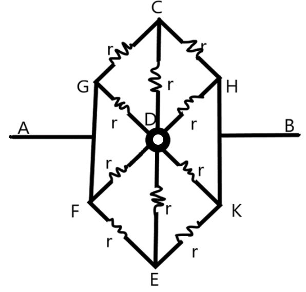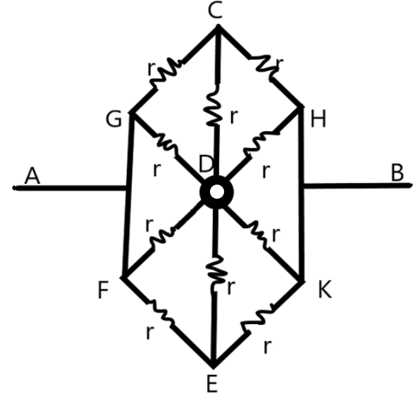
Find the equivalent resistance between the points A and B.


Answer
573k+ views
Hint: We are given a complex circuit with series-parallel connections involved. We need to tackle this complexity using the ideas on the circuit networks and the Wheatstone’s bridge condition due to equipotential points, if any.
Complete step by step solution:
We know that it is very easy to find the equivalent resistance of the circuits which just involves series connections and parallel connections. The networks involving series-parallel networks pose a challenge in finding the equivalent resistance.
The Kirchhoff’s loop rule which states that the algebraic sum of the potential drops and the electromotive forces in a closed loop will be zero makes the calculation of the equivalent resistance of the series-parallel networks very easy. The Wheatstone’s bridge condition which is derived from the Kirchhoff’s loop rule states that for a system of resistors in series-parallel connection will have equipotential points at the nodes connecting all the resistors if the ratio of the resistors along the two sides of the point are in an equal ratio. The resistance which connect these points will therefore be no part of the circuit as no current will flow through it.

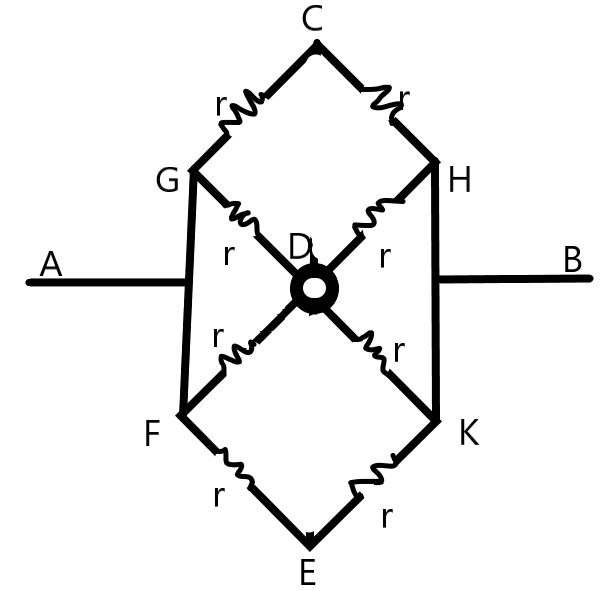
From the figure, we can identify the point C and D, E and D are equipotential points, as a result no current will flow through the resistors CD and ED. Now, we can redraw the simplified circuit as –

Now, we can consider two pairs of resistors which are not connected at D - the upper pair GCH and the lower pair FEK. They are parallel and their equivalent resistance can be given as –
\[\begin{align}
& {{R}_{GCH}}={{R}_{FEK}}=r+r \\
& \Rightarrow {{R}_{GCH}}={{R}_{FEK}}=2r \\
& \text{but,} \\
& {{R}_{GCH}}||{{R}_{FEK}}, \\
& \Rightarrow \dfrac{1}{{{R}_{GCD,FEK}}}=\dfrac{1}{{{R}_{1}}}=\dfrac{1}{2r}+\dfrac{1}{2r} \\
& \Rightarrow \dfrac{1}{{{R}_{1}}}=\dfrac{2}{2r} \\
& \Rightarrow {{R}_{1}}=r \\
\end{align}\]
We can see from the figure that the resistors GD, FD and HD, KD are connected in parallel to each other. The equivalent resistance GFD and HKD can be given as –
\[\begin{align}
& \dfrac{1}{{{R}_{GFD}}}=\dfrac{1}{{{R}_{HKD}}}=\dfrac{1}{r}+\dfrac{1}{r} \\
& \Rightarrow {{R}_{GFD}}={{R}_{HKD}}=\dfrac{r}{2} \\
& \text{But,} \\
& {{R}_{GFD}}\text{ in series with }{{R}_{HKD}} \\
& \Rightarrow {{R}_{GHFK}}={{R}_{2}}=r \\
\end{align}\]
Now, we can find the equivalent resistance of the whole circuit. We can understand that \[{{R}_{1}}||{{R}_{2}}\],
i.e.,
\[\begin{align}
& \dfrac{1}{{{R}_{eq}}}=\dfrac{1}{{{R}_{1}}}+\dfrac{1}{{{R}_{2}}} \\
& \Rightarrow \dfrac{1}{{{R}_{eq}}}=\dfrac{1}{r}+\dfrac{1}{r} \\
& \therefore {{R}_{eq}}=\dfrac{r}{2}\Omega \\
\end{align}\]
The equivalent resistance of the circuit network across A and B is \[\dfrac{r}{2}\Omega \].
This is the required solution.
Note: The resistance of a network is dependent on the type of combination of resistors. From this example, we understand that the resistance can be even lesser than the resistances involved in the circuit. We use this idea in designing electric networks.
Complete step by step solution:
We know that it is very easy to find the equivalent resistance of the circuits which just involves series connections and parallel connections. The networks involving series-parallel networks pose a challenge in finding the equivalent resistance.
The Kirchhoff’s loop rule which states that the algebraic sum of the potential drops and the electromotive forces in a closed loop will be zero makes the calculation of the equivalent resistance of the series-parallel networks very easy. The Wheatstone’s bridge condition which is derived from the Kirchhoff’s loop rule states that for a system of resistors in series-parallel connection will have equipotential points at the nodes connecting all the resistors if the ratio of the resistors along the two sides of the point are in an equal ratio. The resistance which connect these points will therefore be no part of the circuit as no current will flow through it.

From the figure, we can identify the point C and D, E and D are equipotential points, as a result no current will flow through the resistors CD and ED. Now, we can redraw the simplified circuit as –

Now, we can consider two pairs of resistors which are not connected at D - the upper pair GCH and the lower pair FEK. They are parallel and their equivalent resistance can be given as –
\[\begin{align}
& {{R}_{GCH}}={{R}_{FEK}}=r+r \\
& \Rightarrow {{R}_{GCH}}={{R}_{FEK}}=2r \\
& \text{but,} \\
& {{R}_{GCH}}||{{R}_{FEK}}, \\
& \Rightarrow \dfrac{1}{{{R}_{GCD,FEK}}}=\dfrac{1}{{{R}_{1}}}=\dfrac{1}{2r}+\dfrac{1}{2r} \\
& \Rightarrow \dfrac{1}{{{R}_{1}}}=\dfrac{2}{2r} \\
& \Rightarrow {{R}_{1}}=r \\
\end{align}\]
We can see from the figure that the resistors GD, FD and HD, KD are connected in parallel to each other. The equivalent resistance GFD and HKD can be given as –
\[\begin{align}
& \dfrac{1}{{{R}_{GFD}}}=\dfrac{1}{{{R}_{HKD}}}=\dfrac{1}{r}+\dfrac{1}{r} \\
& \Rightarrow {{R}_{GFD}}={{R}_{HKD}}=\dfrac{r}{2} \\
& \text{But,} \\
& {{R}_{GFD}}\text{ in series with }{{R}_{HKD}} \\
& \Rightarrow {{R}_{GHFK}}={{R}_{2}}=r \\
\end{align}\]
Now, we can find the equivalent resistance of the whole circuit. We can understand that \[{{R}_{1}}||{{R}_{2}}\],
i.e.,
\[\begin{align}
& \dfrac{1}{{{R}_{eq}}}=\dfrac{1}{{{R}_{1}}}+\dfrac{1}{{{R}_{2}}} \\
& \Rightarrow \dfrac{1}{{{R}_{eq}}}=\dfrac{1}{r}+\dfrac{1}{r} \\
& \therefore {{R}_{eq}}=\dfrac{r}{2}\Omega \\
\end{align}\]
The equivalent resistance of the circuit network across A and B is \[\dfrac{r}{2}\Omega \].
This is the required solution.
Note: The resistance of a network is dependent on the type of combination of resistors. From this example, we understand that the resistance can be even lesser than the resistances involved in the circuit. We use this idea in designing electric networks.
Recently Updated Pages
Master Class 12 Economics: Engaging Questions & Answers for Success

Master Class 12 Physics: Engaging Questions & Answers for Success

Master Class 12 English: Engaging Questions & Answers for Success

Master Class 12 Social Science: Engaging Questions & Answers for Success

Master Class 12 Maths: Engaging Questions & Answers for Success

Master Class 12 Business Studies: Engaging Questions & Answers for Success

Trending doubts
Which are the Top 10 Largest Countries of the World?

What are the major means of transport Explain each class 12 social science CBSE

Draw a labelled sketch of the human eye class 12 physics CBSE

Why cannot DNA pass through cell membranes class 12 biology CBSE

Differentiate between insitu conservation and exsitu class 12 biology CBSE

Draw a neat and well labeled diagram of TS of ovary class 12 biology CBSE


