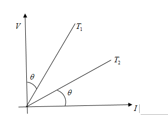
graph \[V - I\] of a conductor at two different temperatures is shown in fig. the ratio of temperature $\dfrac{{{T_1}}}{{{T_2}}}$ is:
(A) ${\tan ^2}\theta $
B) ${\cot ^2}\theta $
C) ${\sec ^2}\theta $
D) $\cos e{c^2}\theta $


Answer
232.8k+ views
Hint As we can see in the figure that $V$ and $I$ are making a right angle triangle, and ${T_1}$ is making angle $\theta $ with voltage and similarly ${T_2}$ is making $\theta $ angle with current. So, we apply trigonometry functions to solve this problem.
Complete Step by step solution
As per figure, we can see that
${T_1} = \tan \theta $
And ${T_2} = \tan \left( {90 - \theta } \right)$
We know that the value of $\tan \left( {90 - \theta } \right)$will become $\cot \theta $
Now, we can say that ${T_2} = \cot \theta $
To find out the ratio of $\dfrac{{{T_1}}}{{{T_2}}}......(1)$
We will put the values of ${T_1}$ and ${T_2}$in equation $(1)$
$\dfrac{{{T_1}}}{{{T_2}}} = \dfrac{{\tan \theta }}{{\cot \theta }}......(2)$
We know that $\cot \theta = \dfrac{1}{{\tan \theta }}$, we put it equation $(2)$
$\dfrac{{{T_1}}}{{{T_2}}} = {\tan ^2}\theta $
Hence, option a is the right answer
Note We should keep in mind trigonometry formulas to solve this problem. As we know that $90 - \theta $means value will lies in first quadrant and in first quadrant $\tan \theta $ will convert in $\cot \theta $, so the value of $\tan \left( {90 - \theta } \right)$ will become $\cot \theta $
Additional information $V - I$ graph stands for a graph of voltage and current, and it shows us properties of a conductor or device. $V - I$ Graph tells valuable information about the resistance in the circuit and breakdown of the electronic component. This information helps us place the electronic component in an electronic circuit. Voltage lies on $y - axis$ and current lies on $x - axis$, resistance tells us the type of the graph. If resistance is constant, the graph will be linear and if resistance is not constant means variable then the graph will be non-linear.
There are different types of $V - I$ graphs, which are as below:
Linear $V - I$ graph
Non-linear $V - I$ graph
$V - I$ Characteristics of SCR
$V - I$ Characteristics of LED
$V - I$ Characteristics of MOSFET
$V - I$ Characteristics of PN Junction Diode
$V - I$ Characteristics of Zener Diode
Recently Updated Pages
JEE Main 2023 April 6 Shift 1 Question Paper with Answer Key

JEE Main 2023 April 6 Shift 2 Question Paper with Answer Key

JEE Main 2023 (January 31 Evening Shift) Question Paper with Solutions [PDF]

JEE Main 2023 January 30 Shift 2 Question Paper with Answer Key

JEE Main 2023 January 25 Shift 1 Question Paper with Answer Key

JEE Main 2023 January 24 Shift 2 Question Paper with Answer Key

Trending doubts
JEE Main 2026: Session 2 Registration Open, City Intimation Slip, Exam Dates, Syllabus & Eligibility

JEE Main 2026 Application Login: Direct Link, Registration, Form Fill, and Steps

Understanding the Angle of Deviation in a Prism

Hybridisation in Chemistry – Concept, Types & Applications

How to Convert a Galvanometer into an Ammeter or Voltmeter

Understanding Uniform Acceleration in Physics

Other Pages
JEE Advanced Marks vs Ranks 2025: Understanding Category-wise Qualifying Marks and Previous Year Cut-offs

Laws of Motion Class 11 Physics Chapter 4 CBSE Notes - 2025-26

Waves Class 11 Physics Chapter 14 CBSE Notes - 2025-26

Mechanical Properties of Fluids Class 11 Physics Chapter 9 CBSE Notes - 2025-26

Thermodynamics Class 11 Physics Chapter 11 CBSE Notes - 2025-26

Units And Measurements Class 11 Physics Chapter 1 CBSE Notes - 2025-26


