


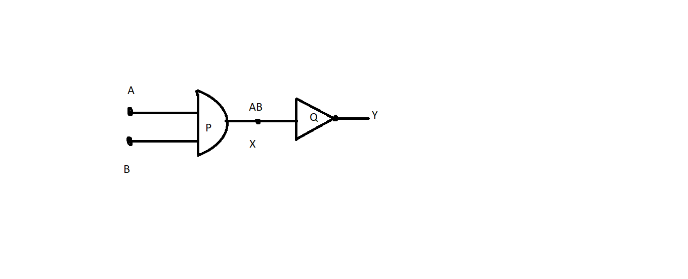
Identify the gates $P$ and $Q$ shown in figure. Write the truth table for the combination of the gates shown. Name the equivalent gates representing this circuit and write its logic symbol.
Answer
579.3k+ views
Hint: The NOT gate is an electrical circuit at its output that generates a reversed representation of the input. This is a NOT-AND door equivalent to an AND door followed by a NOT door. If one of the inputs is low, the performance of all NAND gates is high. The symbol is an AND door with a narrow output circle.
Complete step by step solution:
A symbol whose form is the triangle pointing to the right and at the end of a circle is given to the NO Gate, also known as the "inverter." The loop is referred to as a "bubble of inversion." The NOT attribute is not an AND or OR gate decision-making gate but used to invert or supplement a digital signal. In other words, the output is always the inverse of the input.
This is called the result, the sum or number obtained when two (or more) numbers are multiplied together. AND function is analogous to multiplication in Boolean algebra and therefore its output is the product of its inputs.
The gate $P$ is an AND gate and $Q$ is a NOT gate.
Truth Table for AND(X) and NOT(Y) is given below,
The Equivalent gate would be a NAND gate and its truth table is given below,
Note: Individual logic gates can be wired together to form a number of different switching functions. As we can see from this Interactive Logic Demonstration, three of the fundamental logic gates are: AND, OR and NOT, and all the possible Boolean switching functions are feasible given this set of logic gates, making these gates a complete set of Universal Logic Gates.
Complete step by step solution:
A symbol whose form is the triangle pointing to the right and at the end of a circle is given to the NO Gate, also known as the "inverter." The loop is referred to as a "bubble of inversion." The NOT attribute is not an AND or OR gate decision-making gate but used to invert or supplement a digital signal. In other words, the output is always the inverse of the input.
This is called the result, the sum or number obtained when two (or more) numbers are multiplied together. AND function is analogous to multiplication in Boolean algebra and therefore its output is the product of its inputs.
The gate $P$ is an AND gate and $Q$ is a NOT gate.
Truth Table for AND(X) and NOT(Y) is given below,
| $A$ | $B$ | $X$ | $Y$ |
| $0$ | $0$ | $0$ | $1$ |
| $0$ | $1$ | $0$ | $1$ |
| $1$ | $0$ | $0$ | $1$ |
| $1$ | $1$ | $1$ | $0$ |
The Equivalent gate would be a NAND gate and its truth table is given below,
| $A$ | $B$ | $Y$ |
| $0$ | $0$ | $1$ |
| $0$ | $1$ | $1$ |
| $1$ | $0$ | $1$ |
| $1$ | $1$ | $0$ |
Note: Individual logic gates can be wired together to form a number of different switching functions. As we can see from this Interactive Logic Demonstration, three of the fundamental logic gates are: AND, OR and NOT, and all the possible Boolean switching functions are feasible given this set of logic gates, making these gates a complete set of Universal Logic Gates.
Recently Updated Pages
Master Class 12 Economics: Engaging Questions & Answers for Success
Master Class 12 Physics: Engaging Questions & Answers for Success
Master Class 12 English: Engaging Questions & Answers for Success
Master Class 12 Social Science: Engaging Questions & Answers for Success
Master Class 12 Maths: Engaging Questions & Answers for Success
Master Class 12 Business Studies: Engaging Questions & Answers for Success
Trending doubts
Which are the Top 10 Largest Countries of the World?
What are the major means of transport Explain each class 12 social science CBSE
Draw a labelled sketch of the human eye class 12 physics CBSE
Why cannot DNA pass through cell membranes class 12 biology CBSE
Differentiate between insitu conservation and exsitu class 12 biology CBSE
Draw a neat and well labeled diagram of TS of ovary class 12 biology CBSE