


In a series RLC circuit that is operating above the resonant frequency, the current
A. lags the applied voltage
B. leads the applied voltage
C. is in phase with the applied voltage
D. is zero
Answer
569.1k+ views
Hint: At resonance the capacitive reactance and inductive reactance is equal. At above the resonant frequency the inductive reactance will be greater than the capacitive reactance. So a RLC circuit operating above resonant frequency behaves as a purely inductive circuit. The phase difference between the current and voltage will be the same in this circuit as the inductive circuit.
Formulas used:
${X_C} = \dfrac{1}{{\omega C}}$
${X_L} = \omega L$
${X_L} = {X_C}$
Complete answer:
For a circuit containing resistor, capacitor, and inductor
The inductive reactance is given by ${X_L} = \omega L$
Where $\omega = {\text{ frequency}}$ , $L = {\text{inductance}}$.
And the capacitive reactance is given by ${X_C} = \dfrac{1}{{\omega C}}$.
Current flowing through LCR circuit is given by
$\eqalign{
& V = IZ \cr
& Z = \sqrt {{{\left( {{X_L} - {X_C}} \right)}^2} + {R^2}} \cr} $
Where Z is impedance. At resonance Z will be equal to R only.
We know that inductive circuit current lags voltage and in capacitive circuit current leads voltage.
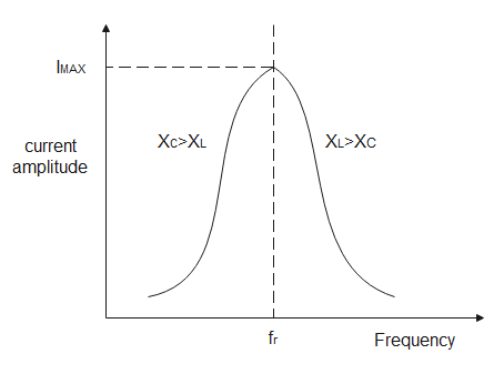
If we draw plot of current passing through LCR circuit VS input frequency it will exactly look like the below diagram
When capacitive reactance equals inductive reactance then that condition is called resonance.
At resonance
$\eqalign{
& {X_L} = {X_C} \cr
& \Rightarrow \omega L = \dfrac{1}{{\omega C}} \cr
& \Rightarrow {\omega ^2} = \dfrac{1}{{LC}} \cr
& \Rightarrow \omega = \dfrac{1}{{\sqrt {LC} }} \cr
& \Rightarrow 2\pi {f_r} = \dfrac{1}{{\sqrt {LC} }} \cr
& \therefore {f_r} = \dfrac{1}{{2\pi \sqrt {LC} }} \cr} $
Where ${f_r}$ is resonating frequency.
In the region where operating frequency is greater than resonating frequency, as per the diagram
${X_L} > {X_C}$. That means the inductor is dominating. So current lags the applied voltage.
Hence option A is correct.
Note:
If we clearly observe the above diagram, at resonating frequency current flowing is maximum because impedance which is resultant of capacitive reactance and inductive reactance and resistance is minimum there. When impedance is minimum, the current flowing will be maximum. Voltage across resistors is always in phase with current. So we are never concerned about the phase difference between the resistor voltage and its current.
Formulas used:
${X_C} = \dfrac{1}{{\omega C}}$
${X_L} = \omega L$
${X_L} = {X_C}$
Complete answer:
For a circuit containing resistor, capacitor, and inductor
The inductive reactance is given by ${X_L} = \omega L$
Where $\omega = {\text{ frequency}}$ , $L = {\text{inductance}}$.
And the capacitive reactance is given by ${X_C} = \dfrac{1}{{\omega C}}$.
Current flowing through LCR circuit is given by
$\eqalign{
& V = IZ \cr
& Z = \sqrt {{{\left( {{X_L} - {X_C}} \right)}^2} + {R^2}} \cr} $
Where Z is impedance. At resonance Z will be equal to R only.
We know that inductive circuit current lags voltage and in capacitive circuit current leads voltage.
If we draw plot of current passing through LCR circuit VS input frequency it will exactly look like the below diagram
When capacitive reactance equals inductive reactance then that condition is called resonance.
At resonance
$\eqalign{
& {X_L} = {X_C} \cr
& \Rightarrow \omega L = \dfrac{1}{{\omega C}} \cr
& \Rightarrow {\omega ^2} = \dfrac{1}{{LC}} \cr
& \Rightarrow \omega = \dfrac{1}{{\sqrt {LC} }} \cr
& \Rightarrow 2\pi {f_r} = \dfrac{1}{{\sqrt {LC} }} \cr
& \therefore {f_r} = \dfrac{1}{{2\pi \sqrt {LC} }} \cr} $
Where ${f_r}$ is resonating frequency.
In the region where operating frequency is greater than resonating frequency, as per the diagram
${X_L} > {X_C}$. That means the inductor is dominating. So current lags the applied voltage.
Hence option A is correct.
Note:
If we clearly observe the above diagram, at resonating frequency current flowing is maximum because impedance which is resultant of capacitive reactance and inductive reactance and resistance is minimum there. When impedance is minimum, the current flowing will be maximum. Voltage across resistors is always in phase with current. So we are never concerned about the phase difference between the resistor voltage and its current.
Recently Updated Pages
Master Class 12 Economics: Engaging Questions & Answers for Success
Master Class 12 Physics: Engaging Questions & Answers for Success
Master Class 12 English: Engaging Questions & Answers for Success
Master Class 12 Social Science: Engaging Questions & Answers for Success
Master Class 12 Maths: Engaging Questions & Answers for Success
Master Class 12 Business Studies: Engaging Questions & Answers for Success
Trending doubts
Which are the Top 10 Largest Countries of the World?
What are the major means of transport Explain each class 12 social science CBSE
Draw a labelled sketch of the human eye class 12 physics CBSE
Why cannot DNA pass through cell membranes class 12 biology CBSE
Differentiate between insitu conservation and exsitu class 12 biology CBSE
Draw a neat and well labeled diagram of TS of ovary class 12 biology CBSE