


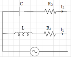
In the above circuit, $C=\dfrac{\sqrt{3}}{2}\mu F$, ${{R}_{2}}=20\Omega $, $L=\dfrac{\sqrt{3}}{10}H$ and ${{R}_{1}}=10\Omega $. Current in $L-{{R}_{1}}$ path is ${{I}_{1}}$ and $C-{{R}_{2}}$ path it is ${{I}_{2}}$. The voltage of the AC source is given by $V=200\sqrt{2}\sin (100t)$ volts. The phase difference between ${{I}_{1}}$ and ${{I}_{2}}$ is:
A. ${{30}^{\circ }}$
B. ${{0}^{\circ }}$
C. ${{150}^{\circ }}$
D. ${{60}^{\circ }}$
Answer
562.8k+ views
Hint:Make use of the equation given for the voltage of an AC source and find the angular frequency of the circuit. Then draw the phasor diagram for both the path and find the phase between the current and the main voltage in both paths.
Formula used:
$V={{V}_{0}}\sin (\omega t)$
$\Rightarrow{{V}_{R1}}={{I}_{1}}{{R}_{1}}$
$\Rightarrow{{V}_{L}}={{I}_{1}}{{X}_{L}}$
$\Rightarrow{{X}_{L}}=\omega L$
$\Rightarrow{{V}_{C}}={{I}_{C}}{{X}_{C}}$
$\Rightarrow{{X}_{C}}=\dfrac{1}{\omega C}$
Here, ${{V}_{0}}$ is the amplitude,$\omega $ is the angular frequency, ${{X}_{L}}$ is the reactance of the inductance, ${{R}_{1}}$, ${{R}_{2}}$ are resistances, ${{X}_{C}}$ is the reactance of the capacitor, C is capacitance and L is inductance.
Complete step by step answer:
The equation for voltage of the source is given as $V={{V}_{0}}\sin (\omega t)$, where ${{V}_{0}}$ is the amplitude and $\omega $ is the angular frequency.It is given that the voltage of the AC source is $V=200\sqrt{2}\sin (100t)$.This means that $\omega =100{{s}^{-1}}$. In the diagram of the circuit, we can see that the capacitor and the resistance ${{R}_{1}}$ in series connection and the inductor and the resistance ${{R}_{2}}$ are also in series connection. Then these both pairs are connected in parallel to an AC source.Let us first the phase diagram for the $L-{{R}_{1}}$ path.The current in this path is said to be ${{I}_{1}}$. When an inductor and a resistance are in series connection, then the voltage across the resistance is in phase with the circuit flowing in that path and the voltage across the inductance leads over current by an phase angle of $\dfrac{\pi }{2}$.
The voltage across the resistance ${{R}_{1}}$ is equal to ${{V}_{R1}}={{I}_{1}}{{R}_{1}}$.
The voltage across the inductor is ${{V}_{L}}={{I}_{1}}{{X}_{L}}$, where ${{X}_{L}}$ is the reactance of the inductance. And ${{X}_{L}}=\omega L$, where $\omega $ is the angular frequency of the source and L is the inductance.Therefore, the phase diagram for the $L-{{R}_{1}}$ path will look like:
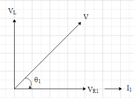
Here V is the amplitude of the source. And it is given that $V=200\sqrt{2}volts$.
From the figure, we get that $\tan {{\theta }_{1}}=\dfrac{{{V}_{L}}}{{{V}_{R1}}}=\dfrac{{{I}_{1}}{{X}_{L}}}{{{I}_{1}}{{R}_{1}}}=\dfrac{{{X}_{L}}}{{{R}_{1}}}$
$\Rightarrow \tan {{\theta }_{1}}=\dfrac{\omega L}{{{R}_{1}}}$
Substitute the given values.
$\Rightarrow \tan {{\theta }_{1}}=\dfrac{100\times \dfrac{\sqrt{3}}{10}}{10}=\sqrt{3}$
$\Rightarrow {{\theta }_{1}}={{\tan }^{-1}}\sqrt{3}={{60}^{\circ }}$
Now, let us draw the phase diagram for the $C-{{R}_{2}}$ path.The current in this path is said to be ${{I}_{2}}$. When a capacitor and a resistance are in series connection, then the voltage across the resistance is in phase with the circuit flowing in that path and the voltage across the inductance lags current by an phase angle of $\dfrac{\pi }{2}$.
The voltage across the resistance ${{R}_{2}}$ is equal to ${{V}_{R2}}={{I}_{2}}{{R}_{2}}$.
The voltage across the capacitor is ${{V}_{C}}={{I}_{C}}{{X}_{C}}$, where ${{X}_{C}}$ is the reactance of the capacitor.
And ${{X}_{C}}=\dfrac{1}{\omega C}$, where C is the capacitance.
Therefore, the phase diagram for the $L-{{R}_{1}}$ path will look like:
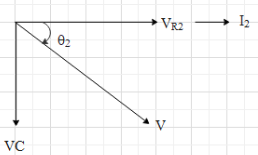
Here the net voltage will be V since both the paths are parallel with the same voltage source.From the figure, we get that $\tan {{\theta }_{2}}=\dfrac{{{V}_{C}}}{{{V}_{R2}}}=\dfrac{{{I}_{2}}{{X}_{C}}}{{{I}_{2}}{{R}_{2}}}=\dfrac{{{X}_{C}}}{{{R}_{2}}}$
$\Rightarrow \tan {{\theta }_{2}}=\dfrac{\dfrac{1}{\omega C}}{{{R}_{2}}}=\dfrac{1}{\omega C{{R}_{2}}}$
Substitute the given values.
$\Rightarrow \tan {{\theta }_{2}}=\dfrac{1}{100\times \dfrac{\sqrt{3}}{2}\times {{10}^{-6}}\times 10}=\dfrac{2\times {{10}^{3}}}{\sqrt{3}}=1154.7$
$\Rightarrow {{\theta }_{2}}={{\tan }^{-1}}(1154.7)\approx {{90}^{\circ }}$.
From the phasor diagram, we can understand that the phase difference between ${{I}_{1}}$ and ${{I}_{2}}$ is ${{\theta }_{1}}+{{\theta }_{2}}={{60}^{\circ }}+{{90}^{\circ }}={{150}^{\circ }}$.
Hence, the correct option is C.
Note: For solving AC circuit, phasor diagrams are used. Here, we do not treat the voltages and current as scalars rather we treat them as vectors. The magnitudes of the vector are equal to the amplitude of the corresponding wave.Since the voltages and current continuously change with time in an AC circuit, we cannot add them algebraically.
Formula used:
$V={{V}_{0}}\sin (\omega t)$
$\Rightarrow{{V}_{R1}}={{I}_{1}}{{R}_{1}}$
$\Rightarrow{{V}_{L}}={{I}_{1}}{{X}_{L}}$
$\Rightarrow{{X}_{L}}=\omega L$
$\Rightarrow{{V}_{C}}={{I}_{C}}{{X}_{C}}$
$\Rightarrow{{X}_{C}}=\dfrac{1}{\omega C}$
Here, ${{V}_{0}}$ is the amplitude,$\omega $ is the angular frequency, ${{X}_{L}}$ is the reactance of the inductance, ${{R}_{1}}$, ${{R}_{2}}$ are resistances, ${{X}_{C}}$ is the reactance of the capacitor, C is capacitance and L is inductance.
Complete step by step answer:
The equation for voltage of the source is given as $V={{V}_{0}}\sin (\omega t)$, where ${{V}_{0}}$ is the amplitude and $\omega $ is the angular frequency.It is given that the voltage of the AC source is $V=200\sqrt{2}\sin (100t)$.This means that $\omega =100{{s}^{-1}}$. In the diagram of the circuit, we can see that the capacitor and the resistance ${{R}_{1}}$ in series connection and the inductor and the resistance ${{R}_{2}}$ are also in series connection. Then these both pairs are connected in parallel to an AC source.Let us first the phase diagram for the $L-{{R}_{1}}$ path.The current in this path is said to be ${{I}_{1}}$. When an inductor and a resistance are in series connection, then the voltage across the resistance is in phase with the circuit flowing in that path and the voltage across the inductance leads over current by an phase angle of $\dfrac{\pi }{2}$.
The voltage across the resistance ${{R}_{1}}$ is equal to ${{V}_{R1}}={{I}_{1}}{{R}_{1}}$.
The voltage across the inductor is ${{V}_{L}}={{I}_{1}}{{X}_{L}}$, where ${{X}_{L}}$ is the reactance of the inductance. And ${{X}_{L}}=\omega L$, where $\omega $ is the angular frequency of the source and L is the inductance.Therefore, the phase diagram for the $L-{{R}_{1}}$ path will look like:
Here V is the amplitude of the source. And it is given that $V=200\sqrt{2}volts$.
From the figure, we get that $\tan {{\theta }_{1}}=\dfrac{{{V}_{L}}}{{{V}_{R1}}}=\dfrac{{{I}_{1}}{{X}_{L}}}{{{I}_{1}}{{R}_{1}}}=\dfrac{{{X}_{L}}}{{{R}_{1}}}$
$\Rightarrow \tan {{\theta }_{1}}=\dfrac{\omega L}{{{R}_{1}}}$
Substitute the given values.
$\Rightarrow \tan {{\theta }_{1}}=\dfrac{100\times \dfrac{\sqrt{3}}{10}}{10}=\sqrt{3}$
$\Rightarrow {{\theta }_{1}}={{\tan }^{-1}}\sqrt{3}={{60}^{\circ }}$
Now, let us draw the phase diagram for the $C-{{R}_{2}}$ path.The current in this path is said to be ${{I}_{2}}$. When a capacitor and a resistance are in series connection, then the voltage across the resistance is in phase with the circuit flowing in that path and the voltage across the inductance lags current by an phase angle of $\dfrac{\pi }{2}$.
The voltage across the resistance ${{R}_{2}}$ is equal to ${{V}_{R2}}={{I}_{2}}{{R}_{2}}$.
The voltage across the capacitor is ${{V}_{C}}={{I}_{C}}{{X}_{C}}$, where ${{X}_{C}}$ is the reactance of the capacitor.
And ${{X}_{C}}=\dfrac{1}{\omega C}$, where C is the capacitance.
Therefore, the phase diagram for the $L-{{R}_{1}}$ path will look like:
Here the net voltage will be V since both the paths are parallel with the same voltage source.From the figure, we get that $\tan {{\theta }_{2}}=\dfrac{{{V}_{C}}}{{{V}_{R2}}}=\dfrac{{{I}_{2}}{{X}_{C}}}{{{I}_{2}}{{R}_{2}}}=\dfrac{{{X}_{C}}}{{{R}_{2}}}$
$\Rightarrow \tan {{\theta }_{2}}=\dfrac{\dfrac{1}{\omega C}}{{{R}_{2}}}=\dfrac{1}{\omega C{{R}_{2}}}$
Substitute the given values.
$\Rightarrow \tan {{\theta }_{2}}=\dfrac{1}{100\times \dfrac{\sqrt{3}}{2}\times {{10}^{-6}}\times 10}=\dfrac{2\times {{10}^{3}}}{\sqrt{3}}=1154.7$
$\Rightarrow {{\theta }_{2}}={{\tan }^{-1}}(1154.7)\approx {{90}^{\circ }}$.
From the phasor diagram, we can understand that the phase difference between ${{I}_{1}}$ and ${{I}_{2}}$ is ${{\theta }_{1}}+{{\theta }_{2}}={{60}^{\circ }}+{{90}^{\circ }}={{150}^{\circ }}$.
Hence, the correct option is C.
Note: For solving AC circuit, phasor diagrams are used. Here, we do not treat the voltages and current as scalars rather we treat them as vectors. The magnitudes of the vector are equal to the amplitude of the corresponding wave.Since the voltages and current continuously change with time in an AC circuit, we cannot add them algebraically.
Recently Updated Pages
Master Class 12 Economics: Engaging Questions & Answers for Success
Master Class 12 Physics: Engaging Questions & Answers for Success
Master Class 12 English: Engaging Questions & Answers for Success
Master Class 12 Social Science: Engaging Questions & Answers for Success
Master Class 12 Maths: Engaging Questions & Answers for Success
Master Class 12 Business Studies: Engaging Questions & Answers for Success
Trending doubts
Which are the Top 10 Largest Countries of the World?
What are the major means of transport Explain each class 12 social science CBSE
Draw a labelled sketch of the human eye class 12 physics CBSE
Why cannot DNA pass through cell membranes class 12 biology CBSE
Differentiate between insitu conservation and exsitu class 12 biology CBSE
Draw a neat and well labeled diagram of TS of ovary class 12 biology CBSE