


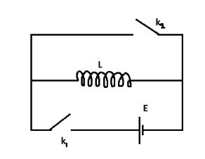
In the circuit shown in the figure, switch ${k_2}$ is open and switch ${k_1}$ is opened at $t = 0$. At time $t = {t_o}$, switch ${k_1}$ is opened and switch ${k_2}$ is simultaneously closed. The variation of inductor current with time is
Answer
582.9k+ views
Hint: when switch ${k_1}$ is closed an emf is induced in the circuit. Applying the formula of emf for the inductor inducing it, we will establish a relation between inductor current and time.
In the above relation, when the boundary conditions of the second circuit alignment is inputted, we will obtain another relation between current and time.
Formulae used: emf is induced in the circuit: $E = L\dfrac{{di}}{{dt}}$.
Where $E$ is the induced emf and is expressed in Volts $(V)$, $L$ is the inductance and is expressed in Henry $(H)$, $di$ is the change in current and is expressed in Ampere $(A)$ and $dt$ is the time taken for the current to change and is expressed in seconds $(s)$.
Step by step solution:When ${k_1}$ is closed, current flows in the circuit due to the battery connected to it. The presence of the inductance coil creates a magnetic flux, which on changing, results in the induction of an electromagnetic force. This is represented by $E$ and is equal to $L\dfrac{{di}}{{dt}}$.
Applying the boundary condition at $t = 0$ we get,
$
E = L\dfrac{{di}}{{dt}} \\
\Rightarrow di = \dfrac{E}{L} \times dt \\
$
Upon integration within the limits of $0 \to {t_o}$ we get,
$
\Rightarrow {\smallint _0}^{{I_{{t_o}}}}di = {\smallint _0}^{{t_o}}\dfrac{E}{L} \times dt \\
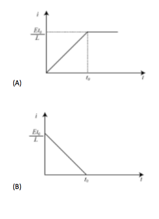
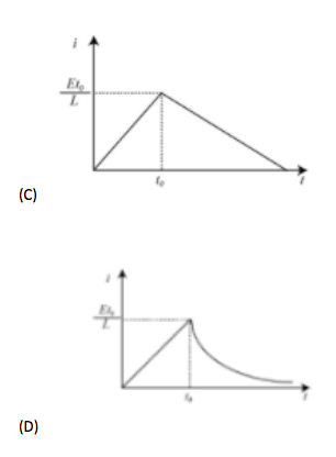
\Rightarrow {I_{{t_o}}} = \dfrac{E}{L}{t_o} \\
$
This linear variation is from $t$ to ${t_o}$.
Now, applying the boundary conditions at $t > {t_o}$ having limits of ${t_o} \to \infty $ we get,
$
E = L\dfrac{{di}}{{dt}} \\
\Rightarrow di = \dfrac{E}{L} \times dt \\
\Rightarrow {\smallint _{{I_{{t_o}}}}}^\infty di = {\smallint ^\infty }_{{t_o}}\dfrac{E}{L} \times dt \\
\Rightarrow {I_\infty } - {I_{{t_o}}} = \dfrac{E}{L}({t_\infty } - {t_o}) \\
$
Which is impossible.
Therefore $L\dfrac{{di}}{{dt}} = 0$ is considered.
This is a constant and therefore there is no variation in inductor current with time.
In conclusion, the correct graph is option A.
Note:The first boundary condition is not $t = 0$. It ranges from $t = 0$ to $t = {t_o}$. Similarly, the second one is also a range, that is, $t = {t_o}$ to $t = {t_\infty }$. Calculations are made to be considered in a given time period and not just at a particular instant of time.
Additional information: A LR circuit is a circuit having a combination of inductor(s) and resistor(s). In AC circuits, they reduce voltage and in DC circuits, the inductor acts as a static resistance. Therefore, the circuit given in the above problem has DC connection because no resistor is present.
In the above relation, when the boundary conditions of the second circuit alignment is inputted, we will obtain another relation between current and time.
Formulae used: emf is induced in the circuit: $E = L\dfrac{{di}}{{dt}}$.
Where $E$ is the induced emf and is expressed in Volts $(V)$, $L$ is the inductance and is expressed in Henry $(H)$, $di$ is the change in current and is expressed in Ampere $(A)$ and $dt$ is the time taken for the current to change and is expressed in seconds $(s)$.
Step by step solution:When ${k_1}$ is closed, current flows in the circuit due to the battery connected to it. The presence of the inductance coil creates a magnetic flux, which on changing, results in the induction of an electromagnetic force. This is represented by $E$ and is equal to $L\dfrac{{di}}{{dt}}$.
Applying the boundary condition at $t = 0$ we get,
$
E = L\dfrac{{di}}{{dt}} \\
\Rightarrow di = \dfrac{E}{L} \times dt \\
$
Upon integration within the limits of $0 \to {t_o}$ we get,
$
\Rightarrow {\smallint _0}^{{I_{{t_o}}}}di = {\smallint _0}^{{t_o}}\dfrac{E}{L} \times dt \\
\Rightarrow {I_{{t_o}}} = \dfrac{E}{L}{t_o} \\
$
This linear variation is from $t$ to ${t_o}$.
Now, applying the boundary conditions at $t > {t_o}$ having limits of ${t_o} \to \infty $ we get,
$
E = L\dfrac{{di}}{{dt}} \\
\Rightarrow di = \dfrac{E}{L} \times dt \\
\Rightarrow {\smallint _{{I_{{t_o}}}}}^\infty di = {\smallint ^\infty }_{{t_o}}\dfrac{E}{L} \times dt \\
\Rightarrow {I_\infty } - {I_{{t_o}}} = \dfrac{E}{L}({t_\infty } - {t_o}) \\
$
Which is impossible.
Therefore $L\dfrac{{di}}{{dt}} = 0$ is considered.
This is a constant and therefore there is no variation in inductor current with time.
In conclusion, the correct graph is option A.
Note:The first boundary condition is not $t = 0$. It ranges from $t = 0$ to $t = {t_o}$. Similarly, the second one is also a range, that is, $t = {t_o}$ to $t = {t_\infty }$. Calculations are made to be considered in a given time period and not just at a particular instant of time.
Additional information: A LR circuit is a circuit having a combination of inductor(s) and resistor(s). In AC circuits, they reduce voltage and in DC circuits, the inductor acts as a static resistance. Therefore, the circuit given in the above problem has DC connection because no resistor is present.
Recently Updated Pages
Master Class 12 Economics: Engaging Questions & Answers for Success
Master Class 12 Physics: Engaging Questions & Answers for Success
Master Class 12 English: Engaging Questions & Answers for Success
Master Class 12 Social Science: Engaging Questions & Answers for Success
Master Class 12 Maths: Engaging Questions & Answers for Success
Master Class 12 Business Studies: Engaging Questions & Answers for Success
Trending doubts
Which are the Top 10 Largest Countries of the World?
What are the major means of transport Explain each class 12 social science CBSE
Draw a labelled sketch of the human eye class 12 physics CBSE
Why cannot DNA pass through cell membranes class 12 biology CBSE
Differentiate between insitu conservation and exsitu class 12 biology CBSE
Draw a neat and well labeled diagram of TS of ovary class 12 biology CBSE