


In the given circuit, the AC source has $\omega = 100rad - {\operatorname{s} ^{ - 1}}$. Considering the inductor and capacitor to be ideal, the correct choice(s) is(are):
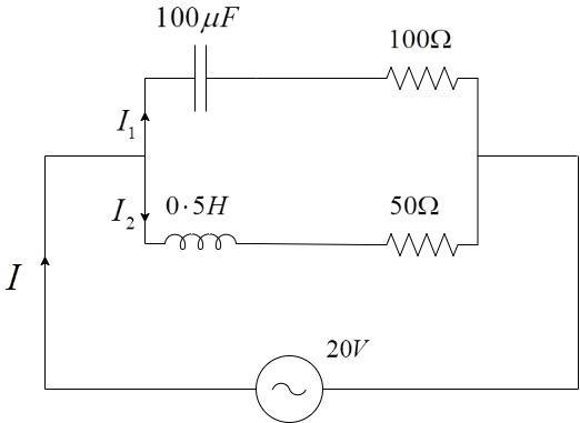
A) The current through the circuit, I is 0.3A
B) The current through the circuit, I is $0 \cdot 3\sqrt 2 A$
C) The voltage across $100\Omega $ resistor = $10\sqrt 2 V$
D) The voltage across $50\Omega $ resistor = 10 V
Answer
580.2k+ views
Hint:If there was a DC source, we could have directly considered the parallel combination of resistors and calculated the net current from the total resistance. As there is an AC source, along with the resistances, we have to also, account for the reactances offered by the inductor and the capacitor, while calculating the branch currents across the branches.
Also, we cannot directly add the impedances as we do in parallel circuits, since the values will be in different phases. So, we have to draw a phasor diagram to solve for the net impedance and hence, the net current in the circuit.
Complete step by step solution:
We have to calculate the individual currents in the branches.
The impedance is the obstruction offered to the flow of A.C current in the circuit.
To find the net impedance in the circuit, we have to individually calculate the impedance of the top branch and then, the individual currents and then, we can add the phasors.
Impedance in the lower branch, ${Z_1} = \sqrt {X_L^2 + {R_1}^2} $
${{Z}_{1}}=\sqrt{{{\left( \omega L \right)}^{2}}+R_{1}^{2}}$
Given the angular frequency, $\omega = 100rad - {s^{ - 1}}$
Inductance, $L = 0 \cdot 5H$
Resistance in the lower branch, ${R_1} = 50\Omega $
Substituting, we get –
\[{Z_1} = \sqrt {{{\left( {\omega L} \right)}^2} + {R_1}^2} \]
\[{Z_1} = \sqrt {{{\left( {100 \times 0 \cdot 5} \right)}^2} + {{50}^2}} \]
$ \Rightarrow {Z_1} = \sqrt {{{50}^2} + {{50}^2}} $
$ \Rightarrow {Z_1} = \sqrt {{{50}^2} \times 2} $
$ \Rightarrow {Z_1} = 50\sqrt 2 \Omega $
The direction, ${\theta _1} = {\tan ^{ - 1}}\left( {\dfrac{{{X_L}}}{R}} \right) = {\tan ^{ - 1}}\left( {\dfrac{{50}}{{50}}} \right) = {45^ \circ }$
Current through the lower branch, ${I_1} = \dfrac{V}{{{Z_1}}} = \dfrac{{20}}{{50\sqrt 2 }}$
Similarly,
Impedance in the upper branch, ${Z_2} = \sqrt {X_C^2 + {R_2}^2} $
\[{Z_2} = \sqrt {{{\left( {\dfrac{1}{{\omega C}}} \right)}^2} + {R_2}^2} \]
Given the angular frequency, $\omega = 100rad - {s^{ - 1}}$
Capacitance, $C = 100\mu F$
Resistance in the upper branch, ${R_2} = 100\Omega $
Substituting, we get –
\[{Z_2} = \sqrt {{{\left( {\dfrac{1}{{\omega C}}} \right)}^2} + {R_2}^2} \]
\[{Z_2} = \sqrt {{{\left( {\dfrac{1}{{100 \times 100 \times {{10}^{ - 6}}}}} \right)}^2} + {{100}^2}} \]
\[ \Rightarrow {Z_2} = \sqrt {{{\left( {\dfrac{1}{{{{10}^4} \times {{10}^{ - 6}}}}} \right)}^2} + {{100}^2}} \]
\[ \Rightarrow {Z_2} = \sqrt {{{\left( {\dfrac{1}{{{{10}^{ - 2}}}}} \right)}^2} + {{100}^2}} \]
\[ \Rightarrow {Z_2} = \sqrt {{{100}^2} + {{100}^2}} \]
\[ \Rightarrow {Z_2} = 100\sqrt 2 \Omega \]
The direction, ${\theta _2} = {\tan ^{ - 1}}\left( {\dfrac{{{X_C}}}{R}} \right) = {\tan ^{ - 1}}\left( {\dfrac{{100}}{{100}}} \right) = {45^ \circ }$
Current through the upper branch, ${I_2} = \dfrac{V}{{{Z_2}}} = \dfrac{{20}}{{100\sqrt 2 }}$
Therefore, the current in the upper branch is ${I_2} = \dfrac{{20}}{{100\sqrt 2 }}A$ at ${45^ \circ }$ and the impedance in the lower branch is ${I_1} = \dfrac{{20}}{{50\sqrt 2 }}A$ at ${45^ \circ }$. Plotting them on the phasor diagram, we get –
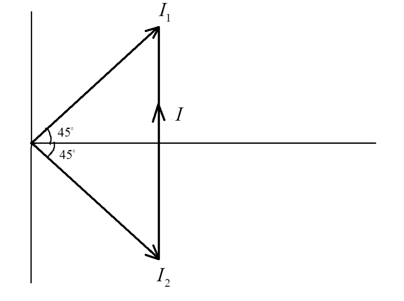
From the phasor, the net current I, is the vector sum of the individual currents. From the above figure, we get –
Magnitude of I,
$I = \sqrt {I_1^2 + I_2^2} $
Thus, $I = \sqrt {{{\left( {0 \cdot 28} \right)}^2} + {{\left( {0 \cdot 141} \right)}^2}} = \sqrt {0 \cdot 098} = 0 \cdot 313A \sim 0 \cdot 3A$
The net current in the circuit, $I = 0 \cdot 3A$
Voltage across the $100\Omega $ resistor is given by, $V = {I_1}R = \dfrac{{20}}{{50\sqrt 2 }} \times 50 = \dfrac{{20}}{{\sqrt 2 }} = \dfrac{{10 \times 2}}{{\sqrt 2 }} = 10\sqrt 2 V$
Voltage across the $50\Omega $ resistor is given by, $V = {I_2}R = \dfrac{{20}}{{100\sqrt 2 }} \times 50 = \dfrac{{10}}{{\sqrt 2 }} = 7 \cdot 07V$
Thus, Statement-A and Statement-C are the only correct statements in the above question.
The correct options are Option A and Option C.
Note:While solving the problem, the students should always note the direction of the current and the relationship between the voltage and current in the phasor diagram.
Note that the current ${I_1}$ is in the top and current ${I_2}$ is in the bottom because in a capacitor, the current always leads the voltage and in an inductor, the current lags the voltage. The students must remember this, while drawing the phasors.
Complete step by step solution:
We have to calculate the individual currents in the branches.
The impedance is the obstruction offered to the flow of A.C current in the circuit.
To find the net impedance in the circuit, we have to individually calculate the impedance of the top branch and then, the individual currents and then, we can add the phasors.
Impedance in the lower branch, ${Z_1} = \sqrt {X_L^2 + {R_1}^2} $
${{Z}_{1}}=\sqrt{{{\left( \omega L \right)}^{2}}+R_{1}^{2}}$
Given the angular frequency, $\omega = 100rad - {s^{ - 1}}$
Inductance, $L = 0 \cdot 5H$
Resistance in the lower branch, ${R_1} = 50\Omega $
Substituting, we get –
\[{Z_1} = \sqrt {{{\left( {\omega L} \right)}^2} + {R_1}^2} \]
\[{Z_1} = \sqrt {{{\left( {100 \times 0 \cdot 5} \right)}^2} + {{50}^2}} \]
$ \Rightarrow {Z_1} = \sqrt {{{50}^2} + {{50}^2}} $
$ \Rightarrow {Z_1} = \sqrt {{{50}^2} \times 2} $
$ \Rightarrow {Z_1} = 50\sqrt 2 \Omega $
The direction, ${\theta _1} = {\tan ^{ - 1}}\left( {\dfrac{{{X_L}}}{R}} \right) = {\tan ^{ - 1}}\left( {\dfrac{{50}}{{50}}} \right) = {45^ \circ }$
Current through the lower branch, ${I_1} = \dfrac{V}{{{Z_1}}} = \dfrac{{20}}{{50\sqrt 2 }}$
Similarly,
Impedance in the upper branch, ${Z_2} = \sqrt {X_C^2 + {R_2}^2} $
\[{Z_2} = \sqrt {{{\left( {\dfrac{1}{{\omega C}}} \right)}^2} + {R_2}^2} \]
Given the angular frequency, $\omega = 100rad - {s^{ - 1}}$
Capacitance, $C = 100\mu F$
Resistance in the upper branch, ${R_2} = 100\Omega $
Substituting, we get –
\[{Z_2} = \sqrt {{{\left( {\dfrac{1}{{\omega C}}} \right)}^2} + {R_2}^2} \]
\[{Z_2} = \sqrt {{{\left( {\dfrac{1}{{100 \times 100 \times {{10}^{ - 6}}}}} \right)}^2} + {{100}^2}} \]
\[ \Rightarrow {Z_2} = \sqrt {{{\left( {\dfrac{1}{{{{10}^4} \times {{10}^{ - 6}}}}} \right)}^2} + {{100}^2}} \]
\[ \Rightarrow {Z_2} = \sqrt {{{\left( {\dfrac{1}{{{{10}^{ - 2}}}}} \right)}^2} + {{100}^2}} \]
\[ \Rightarrow {Z_2} = \sqrt {{{100}^2} + {{100}^2}} \]
\[ \Rightarrow {Z_2} = 100\sqrt 2 \Omega \]
The direction, ${\theta _2} = {\tan ^{ - 1}}\left( {\dfrac{{{X_C}}}{R}} \right) = {\tan ^{ - 1}}\left( {\dfrac{{100}}{{100}}} \right) = {45^ \circ }$
Current through the upper branch, ${I_2} = \dfrac{V}{{{Z_2}}} = \dfrac{{20}}{{100\sqrt 2 }}$
Therefore, the current in the upper branch is ${I_2} = \dfrac{{20}}{{100\sqrt 2 }}A$ at ${45^ \circ }$ and the impedance in the lower branch is ${I_1} = \dfrac{{20}}{{50\sqrt 2 }}A$ at ${45^ \circ }$. Plotting them on the phasor diagram, we get –
From the phasor, the net current I, is the vector sum of the individual currents. From the above figure, we get –
Magnitude of I,
$I = \sqrt {I_1^2 + I_2^2} $
Thus, $I = \sqrt {{{\left( {0 \cdot 28} \right)}^2} + {{\left( {0 \cdot 141} \right)}^2}} = \sqrt {0 \cdot 098} = 0 \cdot 313A \sim 0 \cdot 3A$
The net current in the circuit, $I = 0 \cdot 3A$
Voltage across the $100\Omega $ resistor is given by, $V = {I_1}R = \dfrac{{20}}{{50\sqrt 2 }} \times 50 = \dfrac{{20}}{{\sqrt 2 }} = \dfrac{{10 \times 2}}{{\sqrt 2 }} = 10\sqrt 2 V$
Voltage across the $50\Omega $ resistor is given by, $V = {I_2}R = \dfrac{{20}}{{100\sqrt 2 }} \times 50 = \dfrac{{10}}{{\sqrt 2 }} = 7 \cdot 07V$
Thus, Statement-A and Statement-C are the only correct statements in the above question.
The correct options are Option A and Option C.
Note:While solving the problem, the students should always note the direction of the current and the relationship between the voltage and current in the phasor diagram.
Note that the current ${I_1}$ is in the top and current ${I_2}$ is in the bottom because in a capacitor, the current always leads the voltage and in an inductor, the current lags the voltage. The students must remember this, while drawing the phasors.
Recently Updated Pages
Master Class 12 Economics: Engaging Questions & Answers for Success
Master Class 12 Physics: Engaging Questions & Answers for Success
Master Class 12 English: Engaging Questions & Answers for Success
Master Class 12 Social Science: Engaging Questions & Answers for Success
Master Class 12 Maths: Engaging Questions & Answers for Success
Master Class 12 Business Studies: Engaging Questions & Answers for Success
Trending doubts
Which are the Top 10 Largest Countries of the World?
What are the major means of transport Explain each class 12 social science CBSE
Draw a labelled sketch of the human eye class 12 physics CBSE
Why cannot DNA pass through cell membranes class 12 biology CBSE
Differentiate between insitu conservation and exsitu class 12 biology CBSE
Draw a neat and well labeled diagram of TS of ovary class 12 biology CBSE