


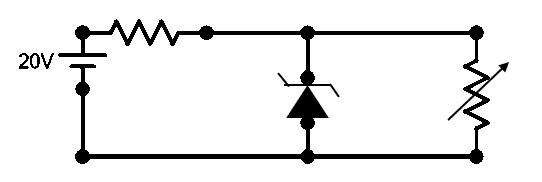
In the given circuit, the voltage across the load is maintained at 12 V. The current in the zener diode varies from 0mA to 50mA. What is the maximum wattage of the diode?
A) 12 W
B) 6 W
C) 0.6 W
D) 1.2 W
Answer
578.1k+ views
Hint: We are given a circuit which consists of a load and a Zener diode which are connected in parallel to each other. We can find the current through each of the devices and thus find the wattage rating of the Zener diode for working without damage.
Complete answer:
We know that Zener diodes are used as voltage regulators in a circuit. It allows a good range of variation in the voltage and can stabilise the output voltage in the given range of current.
Here, we are given a Zener diode of some internal resistance being connected parallel to the load which utilises this voltage stabilisation of the Zener diode. When we look at the circuit, we can understand that the load and the Zener diode are connected in parallel to each other. This makes sure that the voltage drop across both the Zener diode and the load is the same.
We are already given that the constant voltage across the load is 12 V. From the above discussion we found that the voltage across the Zener is also 12 V. Now, it is also given that the current through the Zener diode lies in the range between 0 and 50 mA. So, the maximum current value is also available.
Now, we can find the power dissipated by the Zener diode using the formula –
\[\begin{align}
& P=VI \\
& \Rightarrow \text{ }P=12V\times 50\times {{10}^{-3}}A \\
& \therefore \text{ }P=0.6W \\
\end{align}\]
Therefore, the wattage of the Zener diode is 0.6W.
So, the correct answer is “Option C”.
Note:
For the Zener diodes to be used as a stabilising device, the load should be always connected parallel to it. This is because the voltage is maintained equally only in parallel connections. The resistance shown in series in the figure is the internal resistance of the Zener diode itself.
Recently Updated Pages
Master Class 12 Economics: Engaging Questions & Answers for Success
Master Class 12 Physics: Engaging Questions & Answers for Success
Master Class 12 English: Engaging Questions & Answers for Success
Master Class 12 Social Science: Engaging Questions & Answers for Success
Master Class 12 Maths: Engaging Questions & Answers for Success
Master Class 12 Business Studies: Engaging Questions & Answers for Success
Trending doubts
Which are the Top 10 Largest Countries of the World?
What are the major means of transport Explain each class 12 social science CBSE
Draw a labelled sketch of the human eye class 12 physics CBSE
Why cannot DNA pass through cell membranes class 12 biology CBSE
Differentiate between insitu conservation and exsitu class 12 biology CBSE
Draw a neat and well labeled diagram of TS of ovary class 12 biology CBSE