What is an oscillator? Explain the use of the transistor as an oscillator under the following points:
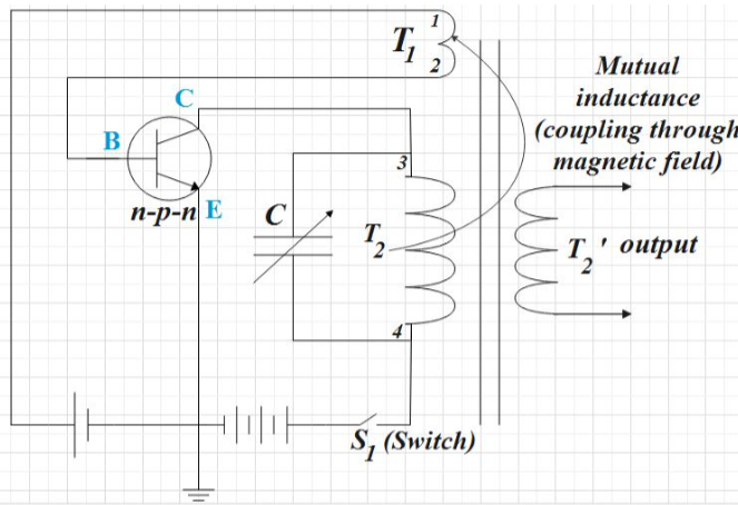
(1) Labeled circuit diagram
(2) Working
Answer
569.1k+ views
Hint: After giving a general definition of the oscillator, you could make a neat labeled circuit diagram of the transistor as an oscillator. Then you could give a brief explanation about its working. Make sure that you give a brief explanation about why in an oscillator the output is said to be self-sustained.
Complete step-by-step solution:
An oscillator can be defined as, that produces a continuous, repeated, alternating waveform without any input. We could say that they basically convert the unidirectional current flow from a DC source into an alternating waveform which is of the desired frequency as decided by its circuit
components.
Now let us discuss the transistor as an oscillator.
(1) Labeled circuit diagram:

(2) Working:
An oscillator gets AC output without any external input signal, that is, we could say that the output of an oscillator is self-sustained.
Let us look at work. A proper bias is applied on switching on ${{S}_{1}}$ which results in a surge of collector current and it flows through coil ${{T}_{2}}$. The current reaches the full amplitude gradually not instantaneously. Inductive coupling occurs for coil ${{T}_{2}}$ and ${{T}_{1}}$, which further results in current through emitter circuit (feedback from the input to output). As a result of this positive feedback, the emitter current also reaches full amplitude. When the maximum collector current is flowing, the transistor becomes saturated and the magnetic field becomes static. Now, there will be feedback from ${{T}_{2}}$ to ${{T}_{1}}$ and so the emitter current fall. And that stage is reached where both ${{I}_{E}}$ and ${{I}_{C}}$ ceases to flow, that is, the transistor is cut-off. Now, the transistor is back to its original state when we switched on the power. Now the whole set of processes repeats itself. That is, initially the transistor goes to saturation, then to cut-off, and then again back to saturation. The time taken for these changes is determined by the constants of the tank circuit or tuned circuit (inductance L of ${{T}_{2}}$ and capacitance C of the capacitor connected parallel to it). Also, the resonance frequency is $\left( \nu \right)$, which determines the frequency of the oscillation of an oscillator.
$\nu =\dfrac{1}{2\pi \sqrt{LC}}$
Note: Positive feedback is the mechanism where a portion of the output power is returned back to the input in phase with the starting power. The feedback is achieved by inductive coupling from coil winding of ${{T}_{1}}$ to coil winding of ${{T}_{2}}$. Also, in the circuit, the base-emitter junction is forward biased and the base-collector junction is reverse biased. Also, here the tank/tuned circuit is on the collector side of the transistor. Hence, it is a tuned collector oscillator.
Complete step-by-step solution:
An oscillator can be defined as, that produces a continuous, repeated, alternating waveform without any input. We could say that they basically convert the unidirectional current flow from a DC source into an alternating waveform which is of the desired frequency as decided by its circuit
components.
Now let us discuss the transistor as an oscillator.
(1) Labeled circuit diagram:

(2) Working:
An oscillator gets AC output without any external input signal, that is, we could say that the output of an oscillator is self-sustained.
Let us look at work. A proper bias is applied on switching on ${{S}_{1}}$ which results in a surge of collector current and it flows through coil ${{T}_{2}}$. The current reaches the full amplitude gradually not instantaneously. Inductive coupling occurs for coil ${{T}_{2}}$ and ${{T}_{1}}$, which further results in current through emitter circuit (feedback from the input to output). As a result of this positive feedback, the emitter current also reaches full amplitude. When the maximum collector current is flowing, the transistor becomes saturated and the magnetic field becomes static. Now, there will be feedback from ${{T}_{2}}$ to ${{T}_{1}}$ and so the emitter current fall. And that stage is reached where both ${{I}_{E}}$ and ${{I}_{C}}$ ceases to flow, that is, the transistor is cut-off. Now, the transistor is back to its original state when we switched on the power. Now the whole set of processes repeats itself. That is, initially the transistor goes to saturation, then to cut-off, and then again back to saturation. The time taken for these changes is determined by the constants of the tank circuit or tuned circuit (inductance L of ${{T}_{2}}$ and capacitance C of the capacitor connected parallel to it). Also, the resonance frequency is $\left( \nu \right)$, which determines the frequency of the oscillation of an oscillator.
$\nu =\dfrac{1}{2\pi \sqrt{LC}}$
Note: Positive feedback is the mechanism where a portion of the output power is returned back to the input in phase with the starting power. The feedback is achieved by inductive coupling from coil winding of ${{T}_{1}}$ to coil winding of ${{T}_{2}}$. Also, in the circuit, the base-emitter junction is forward biased and the base-collector junction is reverse biased. Also, here the tank/tuned circuit is on the collector side of the transistor. Hence, it is a tuned collector oscillator.
Recently Updated Pages
Master Class 12 Economics: Engaging Questions & Answers for Success

Master Class 12 Physics: Engaging Questions & Answers for Success

Master Class 12 English: Engaging Questions & Answers for Success

Master Class 12 Social Science: Engaging Questions & Answers for Success

Master Class 12 Maths: Engaging Questions & Answers for Success

Master Class 12 Business Studies: Engaging Questions & Answers for Success

Trending doubts
Why cannot DNA pass through cell membranes class 12 biology CBSE

Differentiate between insitu conservation and exsitu class 12 biology CBSE

Draw a neat and well labeled diagram of TS of ovary class 12 biology CBSE

In a human foetus the limbs and digits develop after class 12 biology CBSE

AABbCc genotype forms how many types of gametes a 4 class 12 biology CBSE

The correct structure of ethylenediaminetetraacetic class 12 chemistry CBSE


