


Phase difference between voltage and current in a capacitor in an ac circuit is then
$\begin{gathered}
{\text{A}}{\text{. }}\pi \\
{\text{B}}{\text{. }}\dfrac{\pi }{2} \\
{\text{C}}{\text{. 0}} \\
{\text{D}}{\text{. }}\dfrac{\pi }{3} \\
\end{gathered} $
Answer
596.7k+ views
Hint: When we use a capacitor in an ac circuit, it is observed that the voltage and the current are not in phase with each other. The phase difference between the voltage and current can be calculated by comparing the expressions for voltage and current for a capacitor in an ac circuit.
Formula used:
We know that the charge in a capacitor is given as
$Q = CV$
Here Q is the charge stored in the capacitor, C represents the capacitance of the capacitor while V is the voltage for the capacitor.
We know that the current is given as
$I = \dfrac{{dQ}}{{dt}}$
Therefore, for a capacitor we have
$I = C\dfrac{{dV}}{{dt}}{\text{ }}...{\text{(i)}}$
Detailed step by step solution:
Consider that we have a voltage signal given as follows which is fed to an ac circuit containing capacitor.
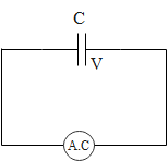
It is given as
$V = {V_0}\sin \omega t{\text{ }}...{\text{(a)}}$
Now we can calculate the current in the circuit using the equation (i) in the following way.
$\begin{gathered}
I = C\dfrac{{dV}}{{dt}} \\
= C\dfrac{d}{{dt}}\left( {{V_0}\sin \omega t} \right) \\
= C{V_0}\omega \cos \omega t \\
\end{gathered} $
This expression for current can also be written in the following way:
$I = C{V_0}\omega \sin \left( {\omega t + \dfrac{\pi }{2}} \right){\text{ }}...{\text{(b)}}$
Now when we compare the equation (b) with equation (a), we notice that the voltage is lagging behind the current in the current. The lag is equal to $\dfrac{\pi }{2}$ radians. Hence, the correct answer is option B.
Note: We can also draw a diagram called phasor diagram which represents the phase difference between current and voltage graphically.
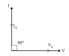
In this diagram we represent the voltage along the x-axis and the current is represented along the y-axis. If we take the voltage in the capacitor to be along the x-axis then since there is a phase difference of 90$^\circ $ between current and voltage, the current is represented along the y-axis at an angle of 90$^\circ $ with respect to the voltage.
Formula used:
We know that the charge in a capacitor is given as
$Q = CV$
Here Q is the charge stored in the capacitor, C represents the capacitance of the capacitor while V is the voltage for the capacitor.
We know that the current is given as
$I = \dfrac{{dQ}}{{dt}}$
Therefore, for a capacitor we have
$I = C\dfrac{{dV}}{{dt}}{\text{ }}...{\text{(i)}}$
Detailed step by step solution:
Consider that we have a voltage signal given as follows which is fed to an ac circuit containing capacitor.
It is given as
$V = {V_0}\sin \omega t{\text{ }}...{\text{(a)}}$
Now we can calculate the current in the circuit using the equation (i) in the following way.
$\begin{gathered}
I = C\dfrac{{dV}}{{dt}} \\
= C\dfrac{d}{{dt}}\left( {{V_0}\sin \omega t} \right) \\
= C{V_0}\omega \cos \omega t \\
\end{gathered} $
This expression for current can also be written in the following way:
$I = C{V_0}\omega \sin \left( {\omega t + \dfrac{\pi }{2}} \right){\text{ }}...{\text{(b)}}$
Now when we compare the equation (b) with equation (a), we notice that the voltage is lagging behind the current in the current. The lag is equal to $\dfrac{\pi }{2}$ radians. Hence, the correct answer is option B.
Note: We can also draw a diagram called phasor diagram which represents the phase difference between current and voltage graphically.
In this diagram we represent the voltage along the x-axis and the current is represented along the y-axis. If we take the voltage in the capacitor to be along the x-axis then since there is a phase difference of 90$^\circ $ between current and voltage, the current is represented along the y-axis at an angle of 90$^\circ $ with respect to the voltage.
Recently Updated Pages
Master Class 12 Economics: Engaging Questions & Answers for Success
Master Class 12 Physics: Engaging Questions & Answers for Success
Master Class 12 English: Engaging Questions & Answers for Success
Master Class 12 Social Science: Engaging Questions & Answers for Success
Master Class 12 Maths: Engaging Questions & Answers for Success
Master Class 12 Business Studies: Engaging Questions & Answers for Success
Trending doubts
Which are the Top 10 Largest Countries of the World?
What are the major means of transport Explain each class 12 social science CBSE
Draw a labelled sketch of the human eye class 12 physics CBSE
Differentiate between insitu conservation and exsitu class 12 biology CBSE
Draw a neat and well labeled diagram of TS of ovary class 12 biology CBSE
Give 10 examples of unisexual and bisexual flowers