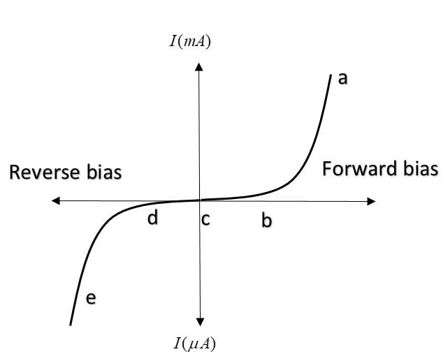
The graph given represents the I-V characteristics of a Zener diode. Which part of the characteristic curve is most relevant for its operation as a voltage regulator?

A. ab
B. bc
C. cd
D. de

Answer
585k+ views
Hint: VI characteristic graph of a p-n junction diode or Zener diode is a graph between the variation of current and voltage. Zener diode is basically a p-n junction diode in which the doping concentration of the electrons and holes is more. It is operative in both the directions, forward and reverse bias.
Complete answer:
A Zener diode works in such a way that the current can flow in both forward and reverse biased conditions.
In forward bias (as shown in the ‘ac’ part of graph), there is a certain point after which the current increases steeply with voltage. This point is marked as ‘b’ and is known as knee voltage. Till this point (from a to b), current increases very slowly with voltage and after this point, it starts behaving like a conductor and the current increases with much higher rate.
In reverse bias (as shown in the ‘ce’ part of graph), there is a certain point in the graph after which current starts increasing with much more rate. This point is marked as ‘d’ and is called Zener voltage (or reverse breakdown voltage). Till this point, the current is negligible and after this point, current changes with a huge rate without much change in voltage.
In fact, the difference between forward and reverse biased conditions is that in forward biased conditions, the current increases with a relatively greater rate of order milli-ampere and in reverse biased conditions, it increases with (micro-ampere) as shown in the graph.
Zener diode is used to regulate voltage i.e. with any amount of increase in current, the voltage change is negligible. This is well defined in the region ‘de’.
Hence option D is correct.
Note: Zener diode is operated in reverse biased conditions. It’s work is to stop the increase in voltage with the increase in current. When it is connected in forward biased conditions, it just allows almost all the current because point ‘b’ is nearer to ‘c’ as compared to ‘d’. Hence it acts as voltage regulator in region ‘de’.
Recently Updated Pages
Master Class 12 Economics: Engaging Questions & Answers for Success

Master Class 12 Physics: Engaging Questions & Answers for Success

Master Class 12 English: Engaging Questions & Answers for Success

Master Class 12 Social Science: Engaging Questions & Answers for Success

Master Class 12 Maths: Engaging Questions & Answers for Success

Master Class 12 Business Studies: Engaging Questions & Answers for Success

Trending doubts
Which are the Top 10 Largest Countries of the World?

What are the major means of transport Explain each class 12 social science CBSE

Draw a labelled sketch of the human eye class 12 physics CBSE

Why cannot DNA pass through cell membranes class 12 biology CBSE

Differentiate between insitu conservation and exsitu class 12 biology CBSE

Draw a neat and well labeled diagram of TS of ovary class 12 biology CBSE


